Expansion Board CAM126B-P-24

The CAM126B-P-24 expansion board provides a rich set of interfaces, as shown below:
Compatible firmware:
Fanconn_V1.6.0_RV1126B_BUILDROOT_EMMC_V1.1_20261028.tar
Fanconn_V1.3.0_RV1126B_DEBIAN12_EMMC_V1.1_20261028.tar.gz
Versions released after October 28, 2026
Expansion Board Interface Definition
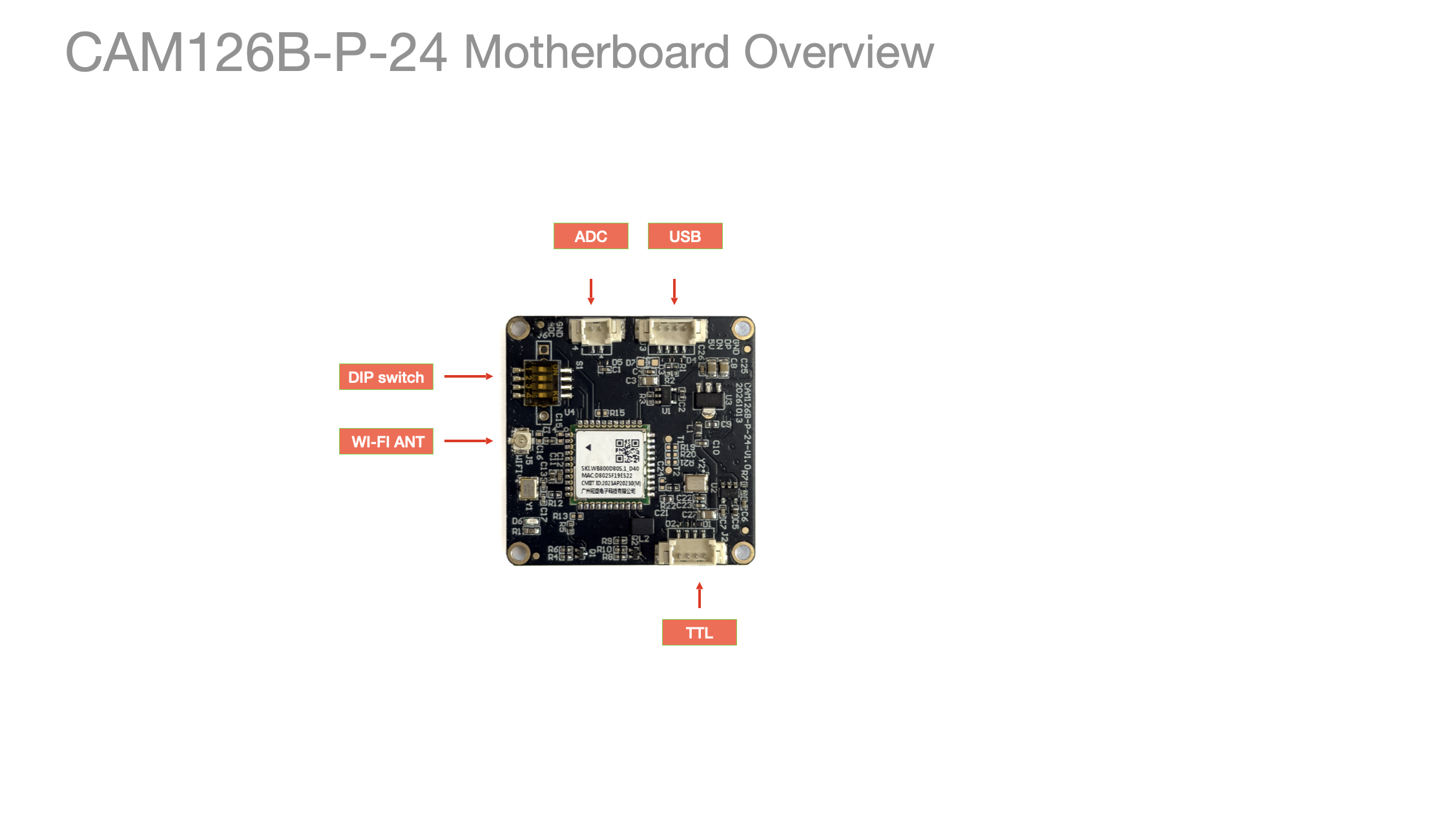
Installation
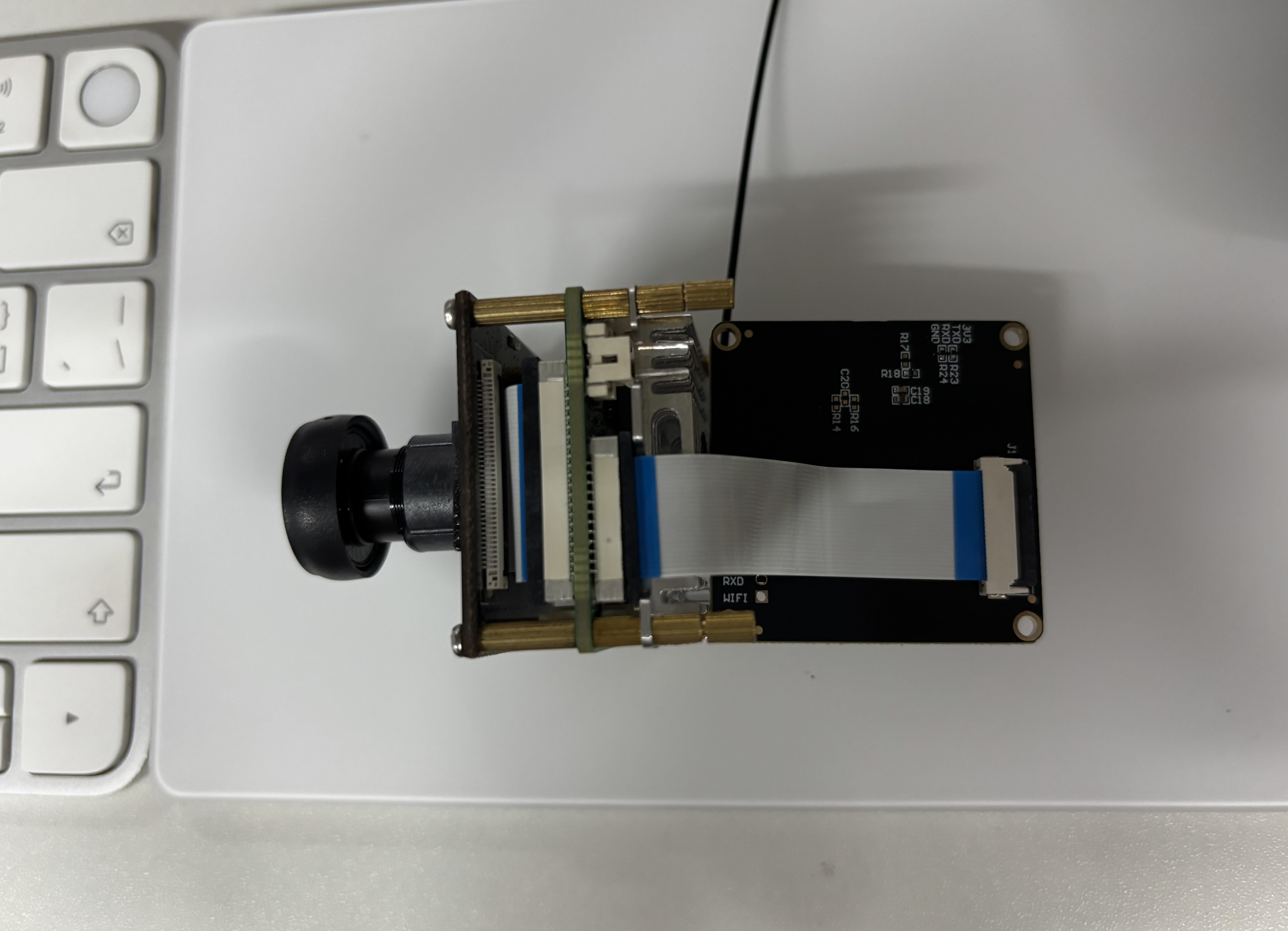
- Pressing down the black latch on the expansion board locks the FPC cable; lifting it releases the cable.
J1 24PIN FPC
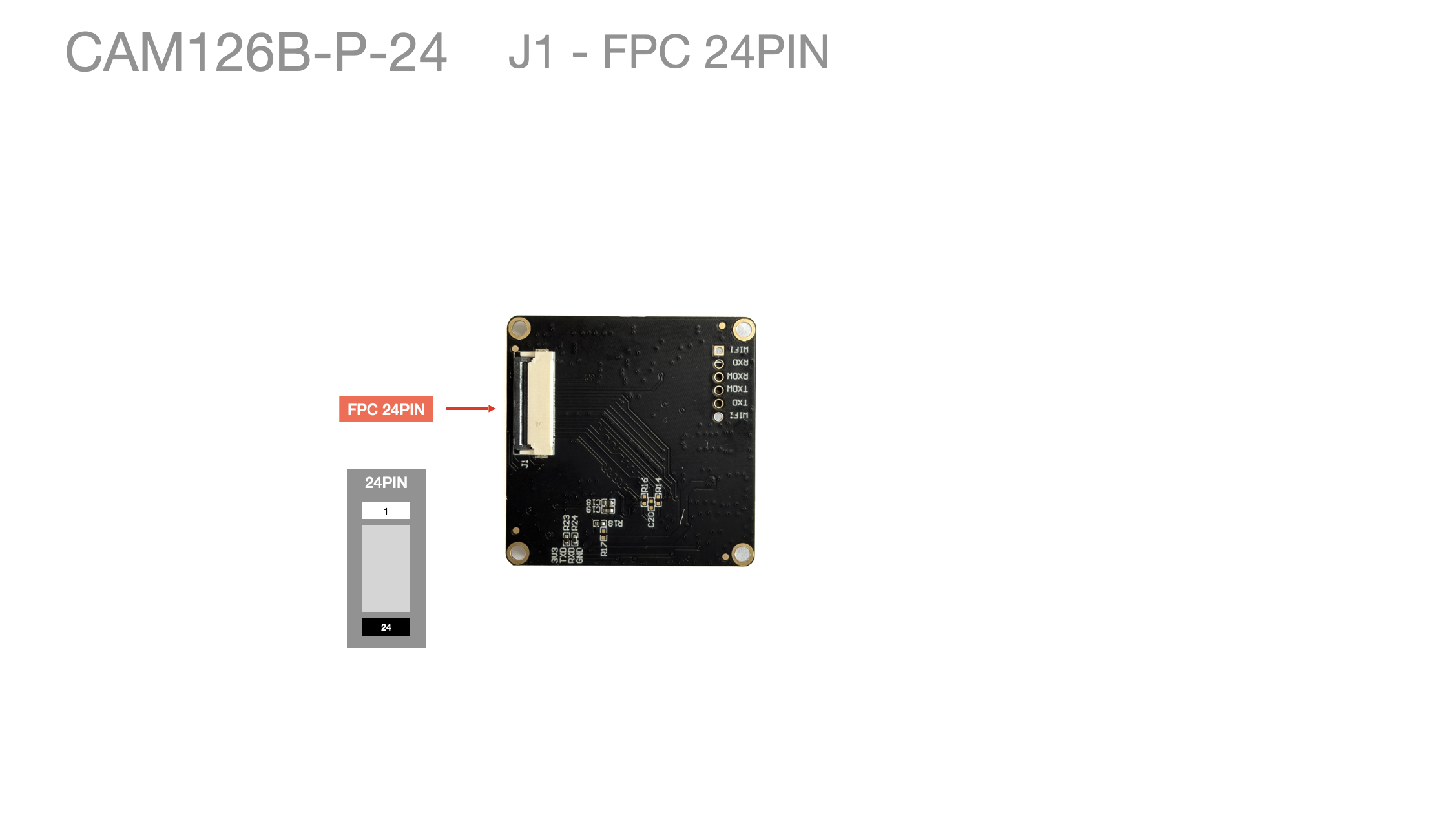
24-pin expansion interface information:
24 PIN 0.5MM FPC connector
The SDIO voltage is 1.8V
Link: https://pan.baidu.com/s/1NyfRuSKcakxMJCZohiFl6A?pwd=fanc Extraction code: fanc Copy this content and open the Baidu Netdisk mobile app for a more convenient operation
| pin | Definition | Ball number | RV1126 | RV1126BP | Pin name CAM126B-P |
|---|---|---|---|---|---|
| 1 | GND | ||||
| 2 | GND | ||||
| 3 | VCC5V0 | ||||
| 4 | VCC5V0 | ||||
| 5 | USB_HOST_DP | Y1 | USB_HOST_DP | ||
| 6 | USB_HOST_DM | Y2 | USB_HOST_DM | ||
| 7 | GND | ||||
| 8 | ADKEY_IN0 | E17 | SARADC_IN0 | ||
| 9 | GND | ||||
| 10 | WIFI_WAKE_HOST | A13 | GPIO1_D1 | GPIO3_B7 | SAI2_SDI1_M0/UART1_RX_M1/I2C5_SDA_M1/GPIO3_B7 |
| 11 | BT_RST | T18 | GPIO3_A5 | GPIO6_A1 | VI_CIF_D1_M0/CAN0_TXD_M1/SAI0_LRCK_M1/PWM1_CH1_M2/UART4_RX_M2/I2C3_SDA_M3/GPIO6_A1 |
| 12 | BT_WAKE | P17 | GPIO3_A6 | GPIO6_A2 | VI_CIF_D2_M0/CAN1_RXD_M1/SAI0_SDO0_M1/PWM1_CH2_M2/UART5_tX_M2/I2C4_SCL_M1/GPIO6_A2 |
| 13 | BT_WAKE_HOST | R17 | GPIO3_A4 | GPIO6_A0 | VI_CIF_D0_M0/CAN0_RXD_M1/SAI0_SCLk_M1/PWM1_CH0_M2/UART4_TX_M2/I2C3_SCL_M3/GPIO6_A0 |
| 14 | WIFI_REG_ON | B13 | GPIO1_D0 | GPIO3_B6 | SPI1_CSN1_M1/SAI2_MCLK_M0/SDMMC1_DETN/UART1_TX_M1/I2C5_SCL_M1/GPIO3_B6 |
| 15 | SDIO_D0 | B16 | GPIO1_B4 | GPIO3_A2 | SDMMC1_D0/I2C1_SCL_M1/GPIO3_A2 |
| 16 | SDIO_D1 | C16 | GPIO1_B5 | GPIO3_A3 | SDMMC1_D1/I2C1_SDA_M1/GPIO3_A3 |
| 17 | SDIO_D2 | D15 | GPIO1_B6 | GPIO3_A4 | SDMMC1_D2/GPIO3_A4 |
| 18 | SDIO_D3 | C15 | GPIO1_B7 | GPIO3_A5 | SDMMC1_D3/GPIO3_A5 |
| 19 | SDIO_CMD | A16 | GPIO1_B3 | GPIO3_A1 | SDMMC1_CMD/GPIO3_A1 |
| 20 | SDIO_CLK | D16 | GPIO1_B2 | GPIO3_A0 | SDMMC1_CLK/GPIO3_A0 |
| 21 | UART0_RTSN | B15 | GPIO1_C0 | GPIO3_A6 | UART2_RTSN_M0/GPIO3_A6 |
| 22 | UART0_TX | C14 | GPIO1_C3 | GPIO3_B1 | SAI2_SDI2_M0/UART2_TX_M0/GPIO3_B1 |
| 23 | UART0_RX | D14 | GPIO1_C2 | GPIO3_B0 | UART2_RX_M0/GPIO3_B0 |
| 24 | UART0_CTSN | A15 | GPIO1_C1 | GPIO3_A7 | UART2_CTSN_M0/GPIO3_A7 |
| Source | Schematic | 1126-1126BP 24pin.xlsx | Schematic | Schematic | Datasheet 1126B-p CAM126B-P-24-V1.0-20261013-原理图.pdf |
J2 TTL
When using TTL, make sure the DIP switch is set to 2/4 to enable it!
When using TTL, make sure the DIP switch is set to 2/4 to enable it!
When using TTL, make sure the DIP switch is set to 2/4 to enable it!
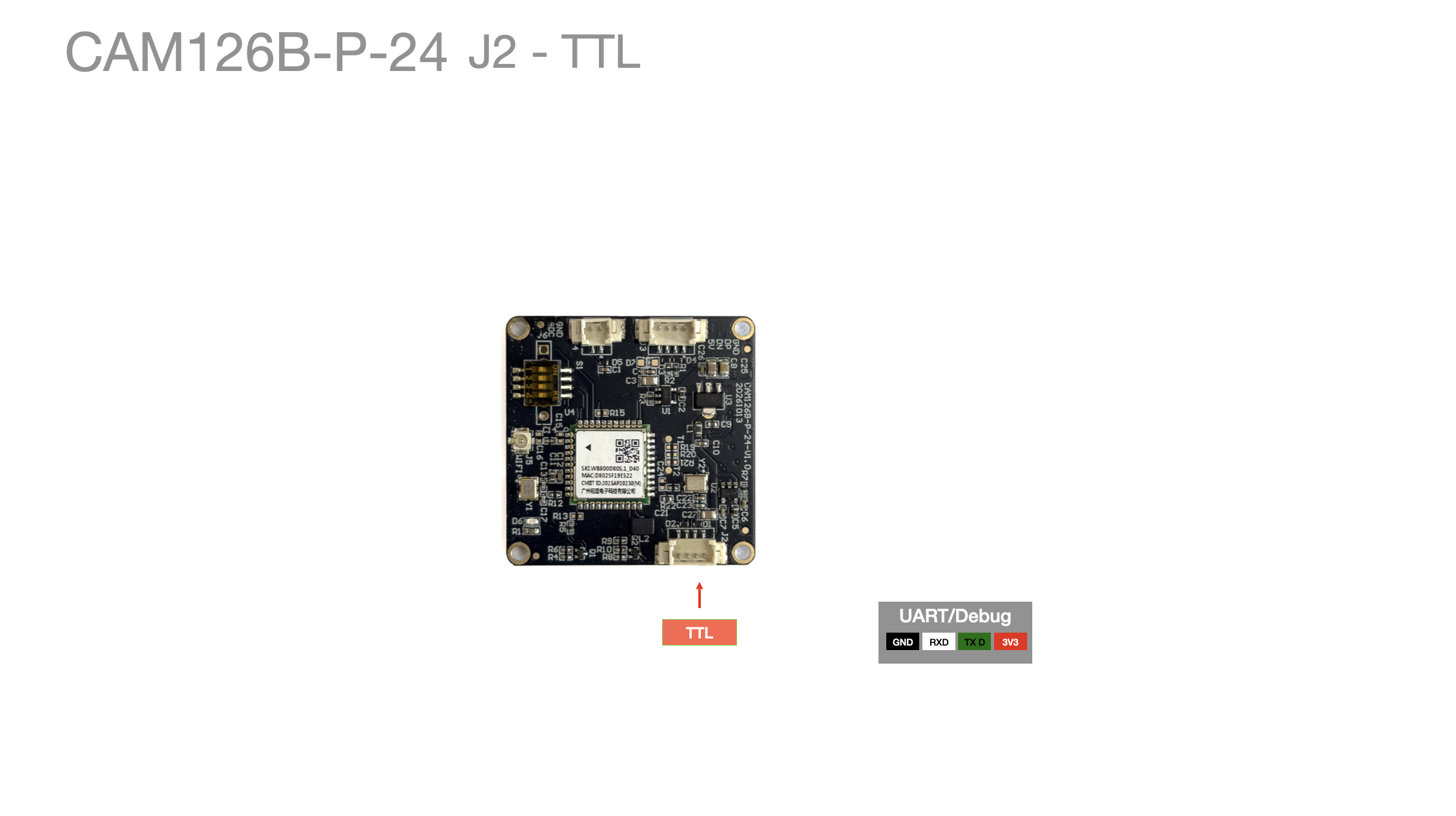
Debug method reference 24PIN expansion TTL
The default interface of CAM126B-P is ttyS2, and the default baud rate is 9600
ttyS2 Serial Port Quick Reference
| Item | Value |
|---|---|
| Device node | /dev/ttyS2 |
| Controller | uart2 @ 0x21170000 (alias serial2 = &uart2) |
| Pin mux | uart2m0 (func 4) |
| TX | 24PIN-22 UART0_TX = GPIO3_B1 (uart2_tx_m0) |
| RX | 24PIN-23 UART0_RX = GPIO3_B0 (uart2_rx_m0) |
| RTS / CTS | 24PIN-21 = GPIO3_A6 (Bluetooth by default) / 24PIN-24 = GPIO3_A7 |
| Default baud rate | 9600 |
J3 USB
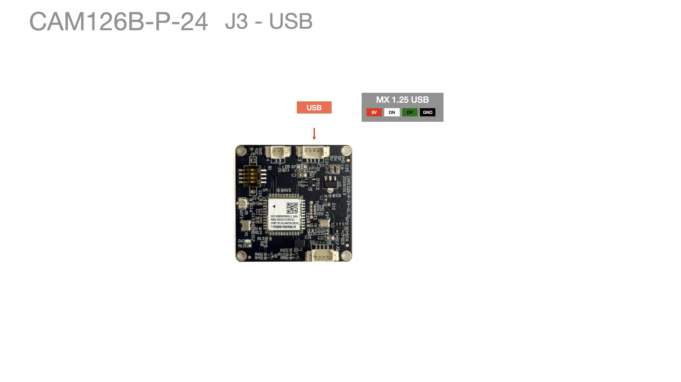
| Pin number | Function description | Reference color |
|---|---|---|
| 1 | GND | Black |
| 2 | OTG_DP | Green/White |
| 3 | OTG_DM | White |
| 4 | VCC5V0 | Red |
J4 ADC Native Interface
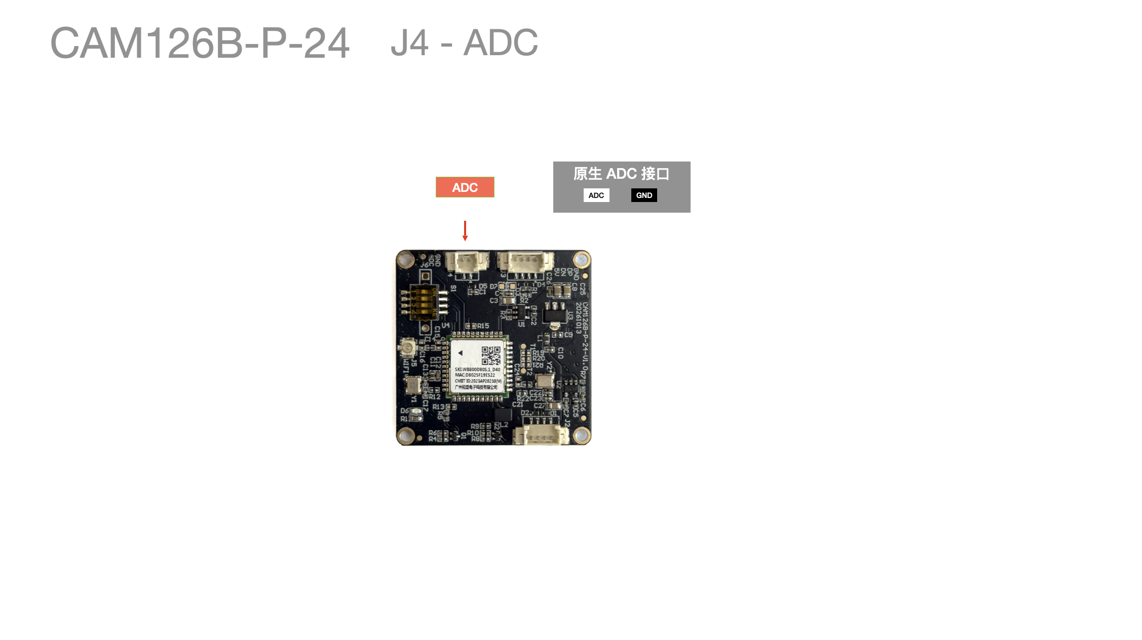
| Pin number | Function description | Reference color |
|---|---|---|
| 1 | GND | Black (ADC function TBD) |
| 2 | ADC | Red (ADC function TBD) |
J5 WIFI Antenna
When using Bluetooth, make sure the DIP switch is set to 1/3 to enable it!
When using Bluetooth, make sure the DIP switch is set to 1/3 to enable it!
When using Bluetooth, make sure the DIP switch is set to 1/3 to enable it!
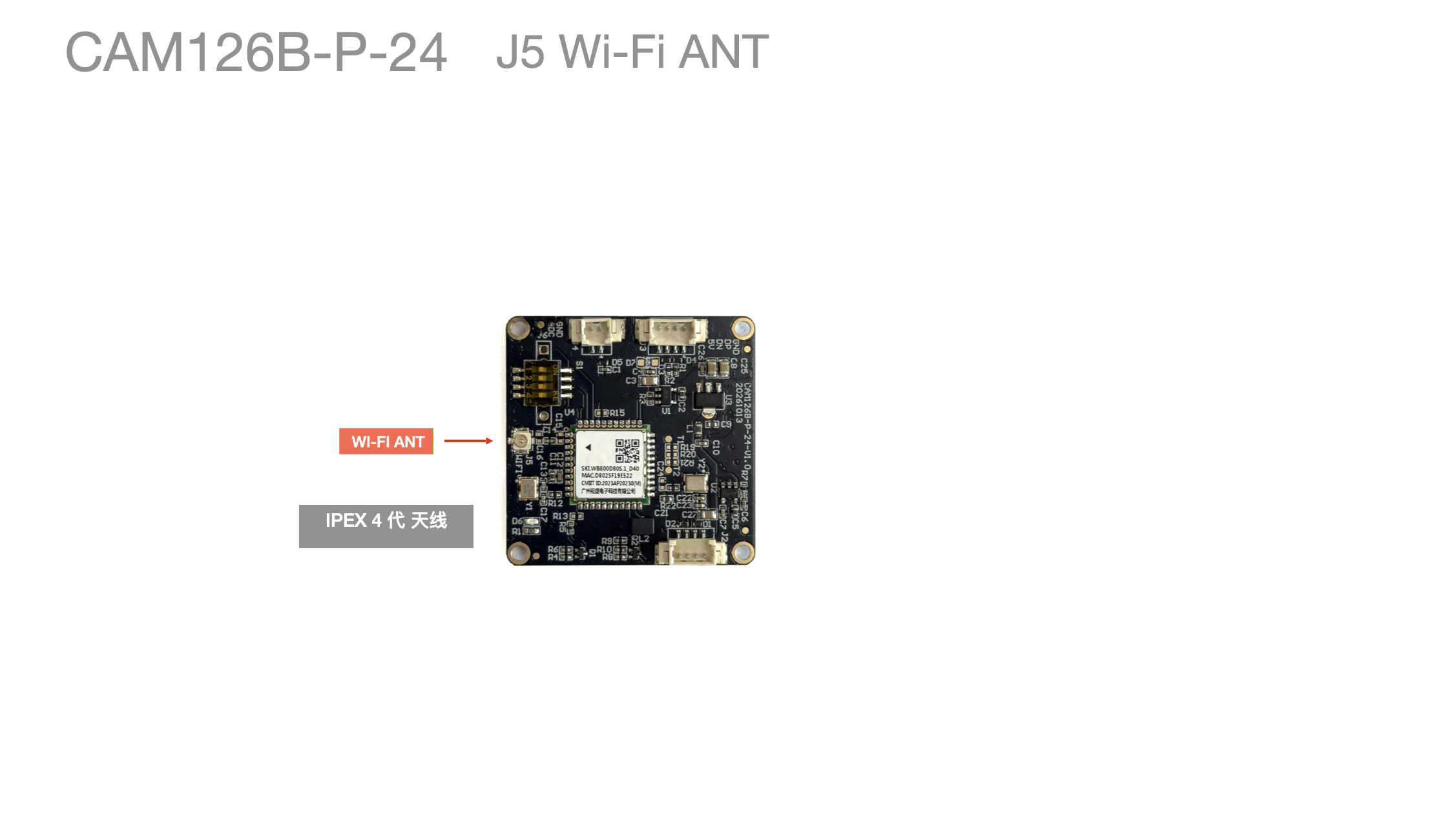
- Bluetooth / BT antenna - IPEX Gen 4
S01 DIP switch
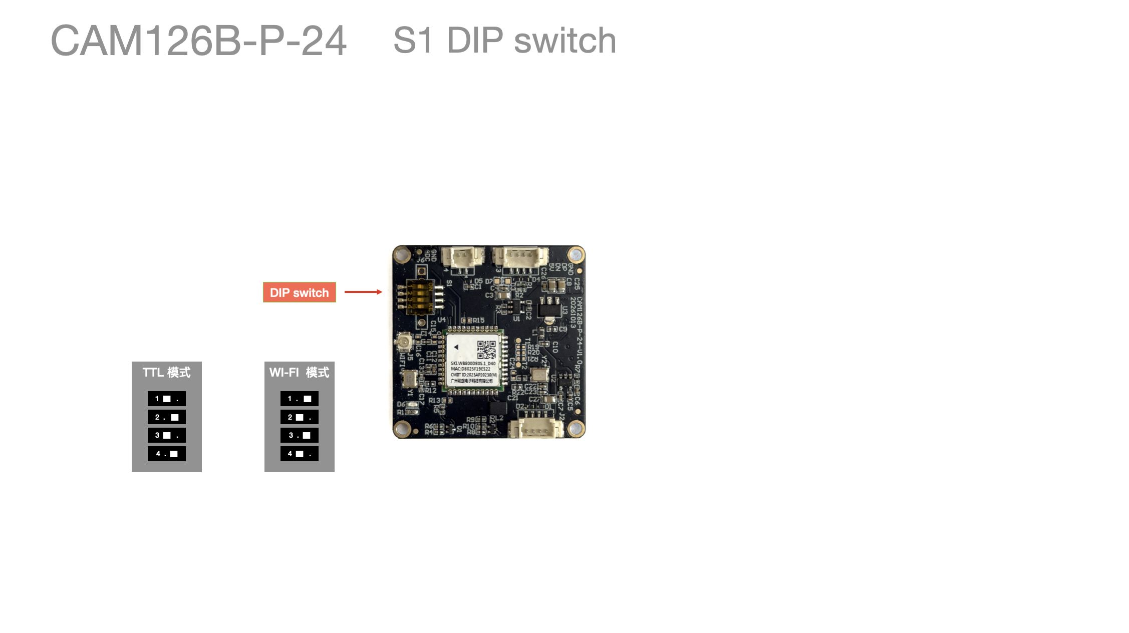
| Pin number | Function description | Description |
|---|---|---|
| 1 | UART RX WIFI | Set the DIP switch to 1 / 3 to enable the WIFI function |
| 2 | UART RX O | Set the DIP switch to 2 / 4 to enable the TTL function |
| 3 | UART TX WIFI | Set the DIP switch to 1 / 3 to enable the WIFI function |
| 4 | UART TX O | Set the DIP switch to 2 / 4 to enable the TTL function |
Schematic
| Schematic | 1126-1126BP
24pin.xlsx | Schematic | Schematic | Datasheet 1126B-p CAM126B-P-24-V1.0-20261013-原理图.pdf|
CAM126B-P can refer to the CAM126 wiring