Interface Debugging

Device Debugging
USB Debugging
Interface info: mx1.25
Connecting the Device
Connect the USB debug device. If the computer USB port has insufficient power supply and cannot start,
| Pin No. | Function Description | Default Wiring Color |
|---|---|---|
| 1 | VCC5V0 | Red |
| 2 | OTG_DM | White |
| 3 | OTG_DP | Green-white |
| 4 | GND | Black |
USB interface
ADB Debugging
You can first download QtScrcpy or
- Download
QtScrcpy-win-x64-v3.3.3.zipand extract it
Extract QtScrcpy-win-x64
- Open it in cmd
Open the extracted QtScrcpy-win-x64 directory
Example: Executing Commands on the Device via ADB
roy@HUAWEIMcMiniM4 ~ % adb devices
List of devices attached
fec3d3812d367ee	device

roy@HUAWEIMcMiniM4 ~ % adb shell

root@rv1126_rv1109:/# uname -a
Linux rv1126_rv1109 4.19.111 #1 SMP PREEMPT Thu Sep 5 12:31:38 UTC 2024 armv7l GNU/Linux
USB Software Info Quick Reference
| Item | Value |
|---|---|
| USB2 PHY | usb2-phy@21400000 (node &usb2phy, board-level &usb2phy_host / &usb2phy_otg) |
| USB3 OTG Controller | usb@21500000 (node &usb_drd_dwc3, UDC name 21500000.usb) |
| Mode | dr_mode = "otg", board-level extcon = <&usb2phy>, phys = <&usb2phy_otg>, maximum-speed = "high-speed" |
| Power Supply | Host port phy-supply = <&vcc5v0_host> |
DTS location: the node is in
arch/arm64/boot/dts/rockchip/rv1126b.dtsi; the board-level configuration is inrv1126bp-evb-v14.dtsi; in the RV1126B SDK it is undersysdrv/source/kernel/arch/arm64/boot/dts/rockchip/.
USB OTG Switching
Below we use the addresses of CAM126B-P: the USB2 PHY is
21400000.usb2-phy, and the dwc3 controller is21500000.usb. (The old addresses on RV1126/RV1109 areff4c0000.usb2-phy/ffd00000.dwc3, which cannot be obtained on 1126B.)
Force USB OTG to switch to Host mode:
echo disconnect > /sys/class/udc/21500000.usb/soft_connect ## (disconnect the usb device connection)
echo host > /sys/devices/platform/21400000.usb2-phy/otg_mode
Force USB OTG to switch to Device mode:
echo peripheral > /sys/devices/platform/21400000.usb2-phy/otg_mode
echo connect > /sys/class/udc/21500000.usb/soft_connect ## (enable the usb device connection)
Force USB OTG to switch to OTG mode:
echo otg > /sys/devices/platform/21400000.usb2-phy/otg_mode
echo connect > /sys/class/udc/21500000.usb/soft_connect ## (enable the usb device connection)
ETH Debugging
Interface info: mx1.25
Viewing the IP
You can view the IP address via the debug serial port, adb, or ssh, for example:
For how to enter ADB, please refer to Example: Executing commands on the device via ADB
roy@HUAWEIMcMiniM4 ~ % adb shell

root@rv1126_rv1109:/# ip addr
1: lo: <LOOPBACK,UP,LOWER_UP> mtu 65536 qdisc noqueue qlen 1000
    link/loopback 00:00:00:00:00:00 brd 00:00:00:00:00:00
    inet 127.0.0.1/8 scope host lo
       valid_lft forever preferred_lft forever
2: eth0: <BROADCAST,MULTICAST,UP,LOWER_UP> mtu 1500 qdisc mq qlen 1000
    link/ether 62:c6:19:eb:91:a5 brd ff:ff:ff:ff:ff:ff
    inet 10.0.0.254/24 brd 10.0.0.255 scope global eth0
       valid_lft forever preferred_lft forever
Connection method
ETH Software Info Quick Reference
| Item | Value |
|---|---|
| Network Device | eth0 |
| Controller | gmac (node ethernet@21c70000) |
| PHY Interface | phy-mode = "rgmii", clock_in_out = "output" |
| PHY Reset | snps,reset-gpio = <&gpio5 RK_PB4 GPIO_ACTIVE_LOW> (board-level rv1126bp-evb1-v12.dts) |
| Default IP | 10.0.0.254/24 (follows the rkipc configuration, see below) |
DTS location: the node is in
arch/arm64/boot/dts/rockchip/rv1126b.dtsi; the board-level configuration is inrv1126bp-evb-v14.dtsi(&gmac) andrv1126bp-evb1-v12.dts(reset-gpio); in the RV1126B SDK it is undersysdrv/source/kernel/arch/arm64/boot/dts/rockchip/.
Check the network port status and negotiated rate:
# Check link status
ip link show eth0

# Check/force the negotiated rate (1000 / 100 / 10)
ethtool eth0
ethtool -s eth0 speed 100 duplex full autoneg off
MIPI Debugging
-
40PIN dual MIPI/LVDS input interface (supports 4lane)
-
Interface definition see the specification
-
Default package:
IMX415IMX307optional
Connection method
MIPI Software Info Quick Reference
| Item | Value |
|---|---|
| Camera I2C | i2c1 @ 0x21110000 (multiplexed as i2c1m2), sensor address imx415=0x1a, sc450ai/sc850sl=0x30 |
| D-PHY | &csi2_dphy0 (node csi2-dphy0) |
| CSI Controller | &mipi0_csi2 (node mipi0-csi2) |
| sensor clock | xvclk = <&cru CLK_MIPI0_OUT2IO>, pinctrl uses cam_clk0_pins |
| sensor reset | reset-gpios = <&gpio4 RK_PA3 GPIO_ACTIVE_LOW> |
| Default package | IMX415 / IMX307 optional |
DTS location: the CSI/D-PHY nodes are in
arch/arm64/boot/dts/rockchip/rv1126b.dtsi; the D-PHY wiring is inrv1126b-evb-cam-csi0.dtsi; the sensor is attached to&i2c1inrv1126bp-evb-cam-csi0.dtsi; in the RV1126B SDK it is undersysdrv/source/kernel/arch/arm64/boot/dts/rockchip/.
Check the currently registered video nodes:
v4l2-ctl --list-devices
Appendix 40pin MIPI interface info:
40 PIN 0.5MM FPC connector, model: X05C2040TZ
You can use the dmesg or logcat commands to view sensor status logs, ensuring the sensor loads normally; otherwise, check the connection or try replacing the camera.
# If the senser is imx307
dmesg | grep imx307

# If the senser is imx415
dmesg | grep imx415
# If the senser is imx307
logcat | grep imx307

# If the senser is imx415
logcat | grep imx415
Reference log for rv1126bp with no camera connected:
root@rv1126bp-buildroot:/# logcat | grep imx415
Jan  1 00:00:01 rv1126bp-buildroot kern.info kernel: [    0.871121] /i2c@21110000/imx415@10: Fixed dependency cycle(s) with /csi2-dphy0
Jan  1 00:00:01 rv1126bp-buildroot kern.info kernel: [    1.344418] imx415 1-0010: driver version: 00.01.08
Jan  1 00:00:01 rv1126bp-buildroot kern.warn kernel: [    1.344450] imx415 1-0010: Get hdr mode failed! no hdr default
Jan  1 00:00:01 rv1126bp-buildroot kern.info kernel: [    1.344484] imx415 1-0010: detect imx415 lane 4
Jan  1 00:00:01 rv1126bp-buildroot kern.warn kernel: [    1.344597] imx415 1-0010: Failed to get power-gpios
Jan  1 00:00:01 rv1126bp-buildroot kern.info kernel: [    1.344617] imx415 1-0010: could not get default pinstate
Jan  1 00:00:01 rv1126bp-buildroot kern.info kernel: [    1.344631] imx415 1-0010: could not get sleep pinstate
Jan  1 00:00:01 rv1126bp-buildroot kern.warn kernel: [    1.344668] imx415 1-0010: supply dvdd not found, using dummy regulator
Jan  1 00:00:01 rv1126bp-buildroot kern.warn kernel: [    1.344850] imx415 1-0010: supply dovdd not found, using dummy regulator
Jan  1 00:00:01 rv1126bp-buildroot kern.warn kernel: [    1.344922] imx415 1-0010: supply avdd not found, using dummy regulator
Jan  1 00:00:01 rv1126bp-buildroot kern.err kernel: [    1.511281] imx415 1-0010: Unexpected sensor id(000000), ret(-5)
Directly Capture the Image and Save it Using the V4L2 Camera Call
Supported formats
v4l2-ctl -d /dev/video12 --list-formats-ext
/tmp/111.yuv
4K
v4l2-ctl -d /dev/video12 \
--set-fmt-video=width=3840,height=2160,pixelformat=NV12 \
--stream-mmap=3 \
--stream-skip=3 \
--stream-to=/tmp/111.yuv \
--stream-count=1 \
--stream-poll
2K
v4l2-ctl -d /dev/video12 \
--set-fmt-video=width=1920,height=1080,pixelformat=NV12 \
--stream-mmap=3 \
--stream-skip=3 \
--stream-to=/tmp/111.yuv \
--stream-count=1 \
--stream-poll
UART Notes
The default interface of CAM126B-P is ttyS2, with a default baud rate of 9600
ttyS2 Serial Port Info Quick Reference
| Item | Value |
|---|---|
| Device Node | /dev/ttyS2 |
| Controller | uart2 @ 0x21170000 (alias serial2 = &uart2) |
| Pin Multiplexing | uart2m0 (func 4) |
| TX | 24PIN-22 UART0_TX = GPIO3_B1 (uart2_tx_m0) |
| RX | 24PIN-23 UART0_RX = GPIO3_B0 (uart2_rx_m0) |
| RTS / CTS | 24PIN-21 = GPIO3_A6 (belongs to Bluetooth by default) / 24PIN-24 = GPIO3_A7 |
| Default Baud Rate | 9600 |
DTS location: the node is in
arch/arm64/boot/dts/rockchip/rv1126b.dtsi; the pins are inrv1126b-pinctrl.dtsi; in the RV1126B SDK it is undersysdrv/source/kernel/arch/arm64/boot/dts/rockchip/.
Check / modify serial port parameters:
# Check current serial port parameters
stty -F /dev/ttyS2 -a

# Modify the baud rate (example: 115200)
stty -F /dev/ttyS2 115200
The connector net names are UART0_*. In the current firmware, 21–24 are connected to the SoC's UART2 uart2m0, and the device node is /dev/ttyS2. The SoC ball numbers of 1–20 have not been verified pin by pin; the description remains as is.
| pin | Definition | Ball No. | RV1126 | RV1126BP | Pin name CAM126B-P |
|---|---|---|---|---|---|
| 1 | GND | ||||
| 2 | GND | ||||
| 3 | VCC5V0 | ||||
| 4 | VCC5V0 | ||||
| 5 | USB_HOST_DP | Y1 | USB_HOST_DP | ||
| 6 | USB_HOST_DM | Y2 | USB_HOST_DM | ||
| 7 | GND | ||||
| 8 | ADKEY_IN0 | E17 | SARADC_IN0 | ||
| 9 | GND | ||||
| 10 | WIFI_WAKE_HOST | A13 | GPIO1_D1 | GPIO3_B7 | SAI2_SDI1_M0/UART1_RX_M1/I2C5_SDA_M1/GPIO3_B7 |
| 11 | BT_RST | T18 | GPIO3_A5 | GPIO6_A1 | VI_CIF_D1_M0/CAN0_TXD_M1/SAI0_LRCK_M1/PWM1_CH1_M2/UART4_RX_M2/I2C3_SDA_M3/GPIO6_A1 |
| 12 | BT_WAKE | P17 | GPIO3_A6 | GPIO6_A2 | VI_CIF_D2_M0/CAN1_RXD_M1/SAI0_SDO0_M1/PWM1_CH2_M2/UART5_tX_M2/I2C4_SCL_M1/GPIO6_A2 |
| 13 | BT_WAKE_HOST | R17 | GPIO3_A4 | GPIO6_A0 | VI_CIF_D0_M0/CAN0_RXD_M1/SAI0_SCLk_M1/PWM1_CH0_M2/UART4_TX_M2/I2C3_SCL_M3/GPIO6_A0 |
| 14 | WIFI_REG_ON | B13 | GPIO1_D0 | GPIO3_B6 | SPI1_CSN1_M1/SAI2_MCLK_M0/SDMMC1_DETN/UART1_TX_M1/I2C5_SCL_M1/GPIO3_B6 |
| 15 | SDIO_D0 | B16 | GPIO1_B4 | GPIO3_A2 | SDMMC1_D0/I2C1_SCL_M1/GPIO3_A2 |
| 16 | SDIO_D1 | C16 | GPIO1_B5 | GPIO3_A3 | SDMMC1_D1/I2C1_SDA_M1/GPIO3_A3 |
| 17 | SDIO_D2 | D15 | GPIO1_B6 | GPIO3_A4 | SDMMC1_D2/GPIO3_A4 |
| 18 | SDIO_D3 | C15 | GPIO1_B7 | GPIO3_A5 | SDMMC1_D3/GPIO3_A5 |
| 19 | SDIO_CMD | A16 | GPIO1_B3 | GPIO3_A1 | SDMMC1_CMD/GPIO3_A1 |
| 20 | SDIO_CLK | D16 | GPIO1_B2 | GPIO3_A0 | SDMMC1_CLK/GPIO3_A0 |
| 21 | UART0_RTSN | B15 | GPIO1_C0 | GPIO3_A6 | UART2_RTSN_M0/GPIO3_A6 |
| 22 | UART0_TX | C14 | GPIO1_C3 | GPIO3_B1 | SAI2_SDI2_M0/UART2_TX_M0/GPIO3_B1 |
| 23 | UART0_RX | D14 | GPIO1_C2 | GPIO3_B0 | UART2_RX_M0/GPIO3_B0 |
| 24 | UART0_CTSN | A15 | GPIO1_C1 | GPIO3_A7 | UART2_CTSN_M0/GPIO3_A7 |
| Source | Schematic | 1126-1126BP 24pin.xlsx | Schematic | Schematic | Datasheet 1126B-p |
The USB-TTL adapter in the figure needs to be purchased and configured by yourself.
The 24 PIN 0.5MM FPC debug board/cable needs to be purchased by yourself
The SDIO voltage is 1.8V
Connection method
Appendix 24pin expansion interface info:
24 PIN 0.5MM FPC connector, model: X05C2024TZ
On the CAM126B-P side, check the baud rate and other information
root@rv1126bp-buildroot:/# stty -F /dev/ttyS2 -a | grep speed
stty: /dev/ttyS2: Inappropriate ioctl for device
speed 9600 baud; line = 0;
On the PC side (USB-TTL), check the baud rate and other information
root@Ubuntu-Magicmini-i5-8500B:~$ stty -F /dev/ttyUSB0 -a | grep speed
speed 9600 baud; rows 0; columns 0; line = 0;
Test method:
## Check on the PC first
cat /dev/ttyUSB0
TX_Test

## Then send from CAM126B-P
echo "TX_Test" > /dev/ttyS2
Test effect
DTS of ttyS2
The running device tree model is Rockchip RV1126B-P EVB1 V12 Board. In the SDK rv1126b_linux_ipc_sdk_release_v1.2.0, the board-level entry only redirects to V14 and has no UART node of its own:
sysdrv/source/kernel/arch/arm64/boot/dts/rockchip/rv1126bp-evb1-v12.dts
#include "rv1126bp-evb-v14.dts"
rv1126bp-evb-v14.dts then includes rv1126bp.dtsi, rv1126bp-evb.dtsi, and rv1126bp-evb-v14.dtsi. rv1126bp.dtsi includes rv1126b.dtsi, and rv1126b.dtsi includes rv1126b-pinctrl.dtsi at the end.
/dev/ttyS2 comes from the alias serial2 = &uart2, in rv1126b.dtsi:
serial2 = &uart2;
The controller default definition is also in rv1126b.dtsi. Here status is disabled, and TX/RX, CTS, and RTS are requested at the same time:
uart2: serial@21170000 {
	compatible = "rockchip,rv1126b-uart", "snps,dw-apb-uart";
	reg = <0x21170000 0x100>;
	interrupts = <GIC_SPI 58 IRQ_TYPE_LEVEL_HIGH>;
	clocks = <&cru SCLK_UART2>, <&cru PCLK_UART2>;
	clock-names = "baudclk", "apb_pclk";
	reg-shift = <2>;
	reg-io-width = <4>;
	dmas = <&dmac 5>, <&dmac 4>;
	pinctrl-names = "default";
	pinctrl-0 = <&uart2m0_xfer_pins &uart2m0_ctsn_pins &uart2m0_rtsn_pins>;
	status = "disabled";
};
The current board enables it in rv1126bp-evb-v14.dtsi; RTS is not on the UART node:
&uart2 {
	status = "okay";
	pinctrl-names = "default";
	pinctrl-0 = <&uart2m0_xfer_pins &uart2m0_ctsn_pins>;
};
In the same file, pin 21 RTS belongs to the Bluetooth node:
wireless-bluetooth {
	compatible = "bluetooth-platdata";
	uart_rts_gpios = <&gpio3 RK_PA6 GPIO_ACTIVE_LOW>;
	pinctrl-names = "default", "rts_gpio";
	pinctrl-0 = <&uart2m0_rtsn_pins>;
	pinctrl-1 = <&uart2_gpios>;
	BT,power_gpio = <&gpio0 RK_PB1 GPIO_ACTIVE_HIGH>;
	status = "okay";
};
wireless-bluetooth {
	uart2_gpios: uart2-gpios {
		rockchip,pins = <3 RK_PA6 RK_FUNC_GPIO &pcfg_pull_none>;
	};
};
The pin multiplexing is in rv1126b-pinctrl.dtsi. m0 is used now, not uart2m1:
uart2m0_xfer_pins: uart2m0-xfer-pins {
	rockchip,pins =
		/* uart2_rx_m0 */
		<3 RK_PB0 4 &pcfg_pull_up>,
		/* uart2_tx_m0 */
		<3 RK_PB1 4 &pcfg_pull_up>;
};

uart2m0_ctsn_pins: uart2m0-ctsn-pins {
	rockchip,pins =
		/* uart2m0_ctsn */
		<3 RK_PA7 4 &pcfg_pull_none>;
};

uart2m0_rtsn_pins: uart2m0-rtsn-pins {
	rockchip,pins =
		/* uart2m0_rtsn */
		<3 RK_PA6 4 &pcfg_pull_none>;
};
Correspondence: RK_PB1 is 22 UART0_TX, RK_PB0 is 23 UART0_RX, RK_PA7 is 24 UART0_CTSN, RK_PA6 is 21 UART0_RTSN.
RV1126B's own board-level DTS does not have GPIO I2C. The same kernel already has gpio_i2c; follow this example:
sysdrv/source/kernel/arch/arm/boot/dts/rv1103-evb-ext-sii902x-bt656-to-hdmi-v10.dtsi
gpio_i2c: i2c@0 {
	compatible = "i2c-gpio";
	gpios = <&gpio3 RK_PA5 GPIO_ACTIVE_HIGH>, /* sda */
		<&gpio3 RK_PA4 GPIO_ACTIVE_HIGH>; /* scl */
	i2c-gpio,delay-us = <2>;		  /* ~100 kHz */
	#address-cells = <1>;
	#size-cells = <0>;
	pinctrl-names = "default";
	pinctrl-0 = <&gpio_i2c_pins>;
	status = "okay";
};
gpio_i2c {
	gpio_i2c_pins: gpio-i2c-pins {
		rockchip,pins =
			/* gpio_i2c_sda */
			<3 RK_PA5 RK_FUNC_GPIO &pcfg_pull_none_smt>,
			/* gpio_i2c_scl */
			<3 RK_PA4 RK_FUNC_GPIO &pcfg_pull_none_smt>;
	};
};
The first entry in gpios is SDA, the second is SCL. In the same directory there is also gpio_i2c0 in rk3506g-test1-v10-audio.dts, with the same properties.
Changing to I2C
GPIO3_B0 and GPIO3_B1 do not have I2C multiplexing in rv1126b-pinctrl.dtsi, so they cannot be changed to &i2c0–&i2c5. i2c0 is currently on i2c0m0 connected to RK809; do not change its pinctrl.
Change pins 22/23 according to the gpio_i2c above. Write it in rv1126bp-evb-v14.dtsi, or write it in the board-level dts that includes it to override. First disable &uart2, otherwise these two pins are still occupied by the serial port:
&uart2 {
	status = "disabled";
};

/ {
	gpio_i2c: i2c@0 {
		compatible = "i2c-gpio";
		gpios = <&gpio3 RK_PB0 GPIO_ACTIVE_HIGH>, /* sda, 24PIN 23 */
			<&gpio3 RK_PB1 GPIO_ACTIVE_HIGH>; /* scl, 24PIN 22 */
		i2c-gpio,delay-us = <2>;		  /* ~100 kHz */
		#address-cells = <1>;
		#size-cells = <0>;
		pinctrl-names = "default";
		pinctrl-0 = <&gpio_i2c_pins>;
		status = "okay";
	};
};

&pinctrl {
	gpio_i2c {
		gpio_i2c_pins: gpio-i2c-pins {
			rockchip,pins =
				/* gpio_i2c_sda,GPIO3_B0 */
				<3 RK_PB0 RK_FUNC_GPIO &pcfg_pull_none_smt>,
				/* gpio_i2c_scl,GPIO3_B1 */
				<3 RK_PB1 RK_FUNC_GPIO &pcfg_pull_none_smt>;
		};
	};
};
SCL and SDA require external pull-ups. Pin 21 is still occupied by wireless-bluetooth; if this pin also needs to be freed, change that node to status = "disabled".
RS-485 Debugging
Interface info: mx1.25
The RS-485 interface is ttyS3, with a default baud rate of 9600
| Pin No. | Function Description |
|---|---|
| 1 | GND |
| 2 | A |
| 3 | B |
The USB-RS485 adapter in the figure needs to be purchased and configured by yourself.
Connection method
On the CAM126B-P side, check the baud rate and other information
root@rv1126_rv1109:/# stty -F /dev/ttyS3 -a | grep speed
speed 9600 baud; rows 0; columns 0; line = 0;
On the PC side (USB-TTL), check the baud rate and other information
root@Ubuntu-Magicmini-i5-8500B:~$ stty -F /dev/ttyUSB0 -a | grep speed
speed 9600 baud; rows 0; columns 0; line = 0;
Test method:
## Check on the PC first
cat /dev/ttyUSB0
TX_Test

## Then send from CAM126B-P
echo "TX_Test" > /dev/ttyS3
Test effect
RS-485 Serial Port Info Quick Reference
| Item | Value |
|---|---|
| Device Node | /dev/ttyS3 |
| Controller | uart3 @ 0x21180000 (alias serial3 = &uart3) |
| Pin Multiplexing | uart3m0 (func 2) |
| TX | GPIO2_A3 (uart3_tx_m0) |
| RX | GPIO2_A2 (uart3_rx_m0) |
| Default Baud Rate | 9600 |
DTS location: the node is in
arch/arm64/boot/dts/rockchip/rv1126b.dtsi; the pins are inrv1126b-pinctrl.dtsi; board-level enabling is inrv1126bp-evb.dtsi/rv1126bp-evb-v14.dtsi; in the RV1126B SDK it is undersysdrv/source/kernel/arch/arm64/boot/dts/rockchip/.
RS-485 is a normal UART with an external 485 level conversion (the TX/RX direction switches automatically); it is equivalent to a normal serial port in software, and the method for changing the baud rate is exactly the same as for ttyS2:
# Check current serial port parameters
stty -F /dev/ttyS3 -a

# Modify the baud rate (example: 115200)
stty -F /dev/ttyS3 115200
The board-level DTS of this SDK does not enable uart3 by default (uart3 in rv1126b.dtsi is status = "disabled"). If /dev/ttyS3 cannot be found in the firmware, you need to enable uart3 in the board-level DTS. It can be added to rv1126bp-evb.dtsi:
/*
 * Enable uart3 as the RS-485 serial port /dev/ttyS3 (multiplexed as uart3m0):
 *   GPIO2_A2 = uart3_rx, GPIO2_A3 = uart3_tx
 */
&uart3 {
	status = "okay";
};
After modification, recompile the kernel DTS and flash it.
Debug Debugging
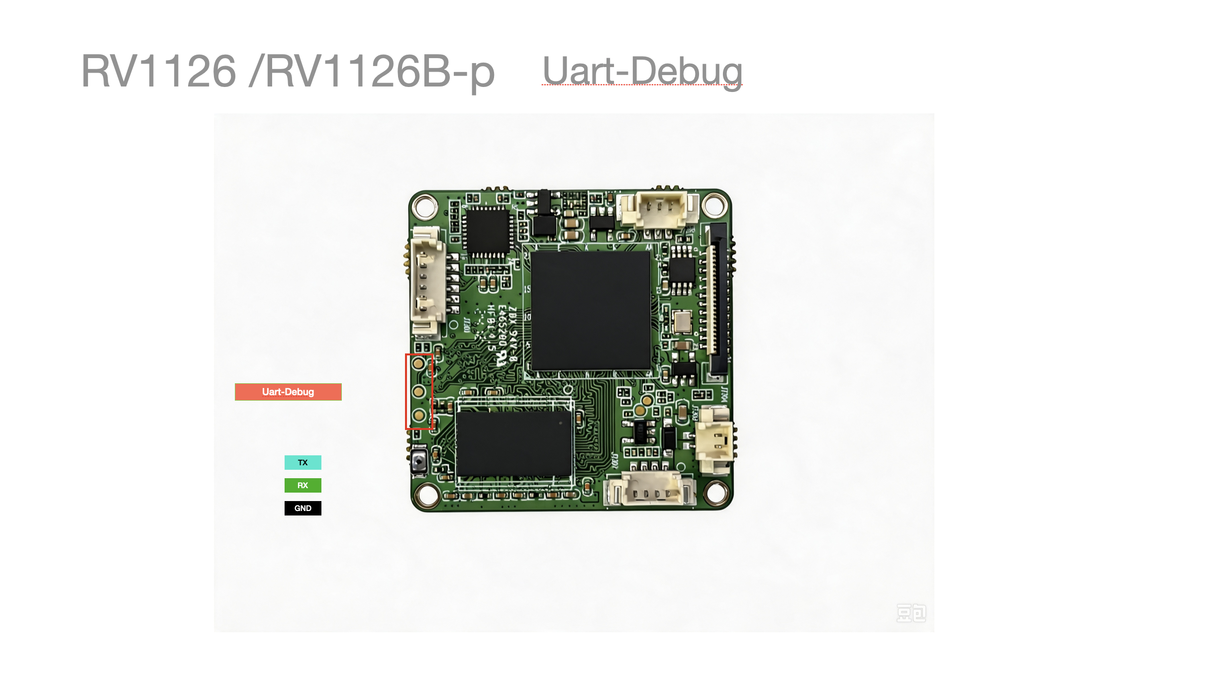
Interface info: pad contacts
Please use TTL debug 1500000 (5个0️⃣)
Linux screen reference usage:
screen /dev/ttyUSB0 1500000
Exit method:
Ctrl+A : quit
You will see the log after powering on:
Bootdev(atags): mmc 0
MMC0: HS200, 200Mhz
PartType 0xfde00000 as drm logo base memory
Model: Rockchip RV1126B-P E 0N/A)
  gpll 1188000 KHz
  aupll 786431 KHz
t 100000 KHz
  aclk_top_root 600000 KHz
  pclk_top_root 100000h0: ethernet@21c70000
Hit key to stop autoboot('CTRL+C'): 0
The USB-TTL adapter in the figure needs to be purchased and configured by yourself.
The debug contacts need to be soldered by yourself.
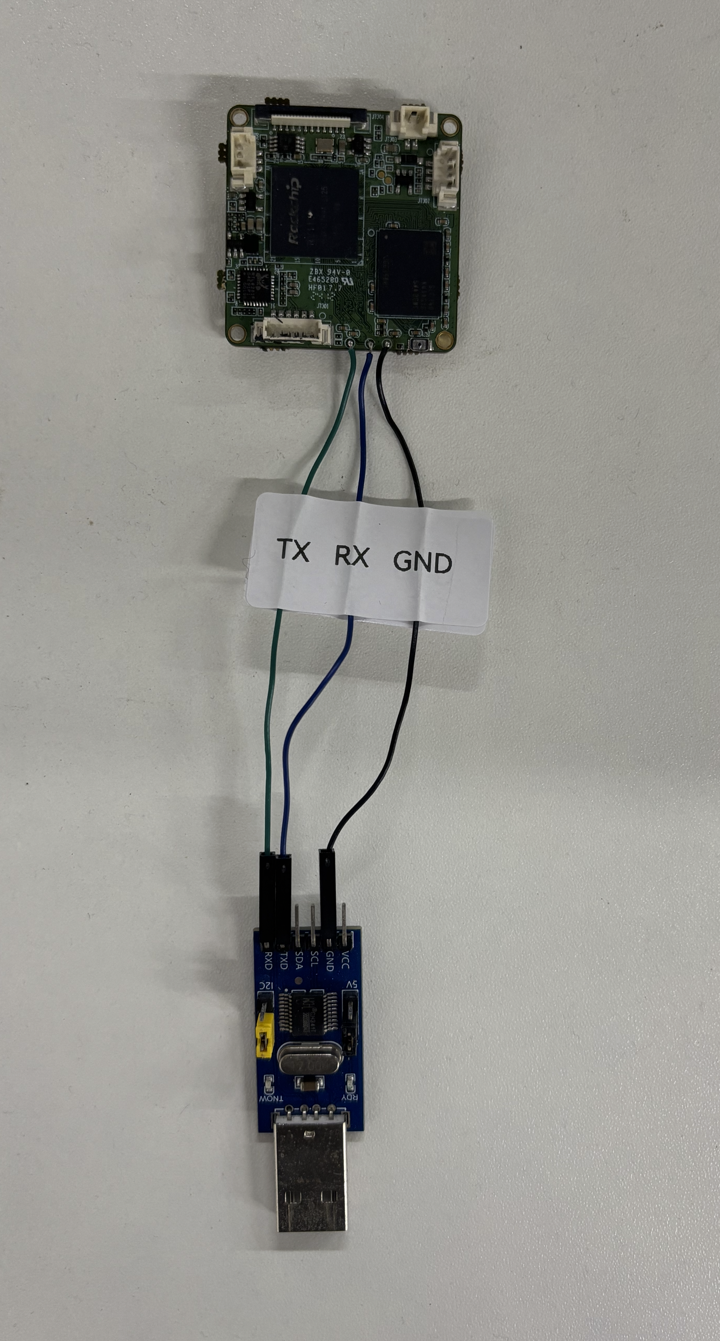
Software Info for the Debug Serial Port
In the default firmware, this debug port is taken over by Rockchip fiq-debugger and registered by the kernel as /dev/ttyFIQ0, corresponding physically to uart0 (serial@20810000), with a baud rate of 1500000 (consistent with the screen above).
| Item | Value |
|---|---|
| Device Node | /dev/ttyFIQ0 |
| Controller | uart0 @ 0x20810000 (alias serial0 = &uart0) |
| Pin Multiplexing | uart0m0: GPIO2_A0 = uart0_rx, GPIO2_A1 = uart0_tx |
| Default Baud Rate | 1500000 |
| Login shell | busybox ::respawn:-/bin/sh runs on /dev/console; when console=ttyFIQ0, it logs in to this debug port |
Related file paths (RV1126B SDK; the kernel source directory is sysdrv/source/kernel, and the DTS files are all under its arch/arm64/boot/dts/rockchip/):
| Content to Change | File Path |
|---|---|
| The actually compiled board-level DTS (model entry) | sysdrv/source/kernel/arch/arm64/boot/dts/rockchip/rv1126bp-evb1-v12.dts |
bootargs, &fiq_debugger switch, &uart0 (change here) | sysdrv/source/kernel/arch/arm64/boot/dts/rockchip/rv1126bp-evb.dtsi |
fiq_debugger node, uart0 node, aliases | sysdrv/source/kernel/arch/arm64/boot/dts/rockchip/rv1126b.dtsi |
Pin multiplexing uart0m0 / uart2m0 | sysdrv/source/kernel/arch/arm64/boot/dts/rockchip/rv1126b-pinctrl.dtsi |
| Login getty / shell (optional) | buildroot/package/busybox/inittab (generated to /etc/inittab in the rootfs) |
bootargs (rv1126bp-evb.dtsi):
chosen {
	bootargs = "earlycon=uart8250,mmio32,0x20810000 console=ttyFIQ0 root=PARTUUID=614e0000-0000 rootwait snd_soc_core.prealloc_buffer_size_kbytes=16 coherent_pool=32K";
};
fiq_debugger controller (defined in rv1126b.dtsi, enabled by the board level):
fiq_debugger: fiq-debugger {
	compatible = "rockchip,fiq-debugger";
	rockchip,serial-id = <0>;      /* 0 = uart0 */
	rockchip,wake-irq = <0>;
	rockchip,irq-mode-enable = <0>;
	rockchip,baudrate = <1500000>; /* only supports 115200 and 1500000 */
	interrupts = <GIC_SPI 240 IRQ_TYPE_LEVEL_HIGH>;
	status = "disabled";           /* change to "okay" in the board-level dtsi */
};
Check the device node:
root@rv1126bp-buildroot:/# ls -l /dev/ttyFIQ0
root@rv1126bp-buildroot:/# dmesg | grep -i fiq
Changing to a Normal ttyS0
If you want to use this debug port as a normal TTL serial port (/dev/ttyS0), you need to disable fiq-debugger, hand uart0 over to the normal 8250 driver, and change the console to ttyS0. Taking rv1126bp-evb.dtsi as an example:
/* Change console from ttyFIQ0 to ttyS0 (earlycon's 0x20810000 is uart0, keep it unchanged) */
chosen {
	bootargs = "earlycon=uart8250,mmio32,0x20810000 console=ttyS0 root=PARTUUID=614e0000-0000 rootwait snd_soc_core.prealloc_buffer_size_kbytes=16 coherent_pool=32K";
};

/* Disable fiq-debugger so uart0 can be taken over by the normal 8250 driver and registered as /dev/ttyS0 */
&fiq_debugger {
	status = "disabled";
};

/* Enable uart0 as a normal serial port */
&uart0 {
	status = "okay";
};
After the change, /dev/console points to /dev/ttyS0, and the login shell will follow automatically; if you want to show a login prompt, you can add ttyS0::respawn:/sbin/getty -L ttyS0 115200 vt100 to /etc/inittab.
Common Linux Commands
Check the Core Temperature
cat /sys/class/thermal/thermal_zone0/temp
cat /sys/class/thermal/thermal_zone1/temp

45200
Divide the output result by 100 to get the temperature in Celsius; the NPU and CPU are together, so they can be regarded as the same