Interface Definition

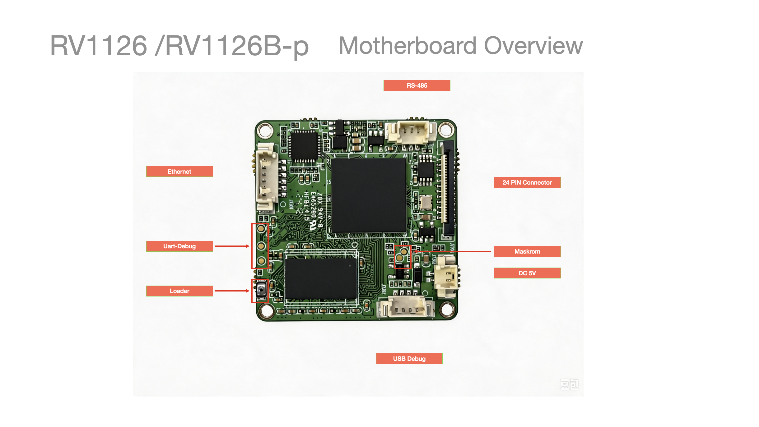
The CAM126 provides a rich set of interfaces, as shown in the figure below:
Complete Device Interface Definition
Ethernet Interface
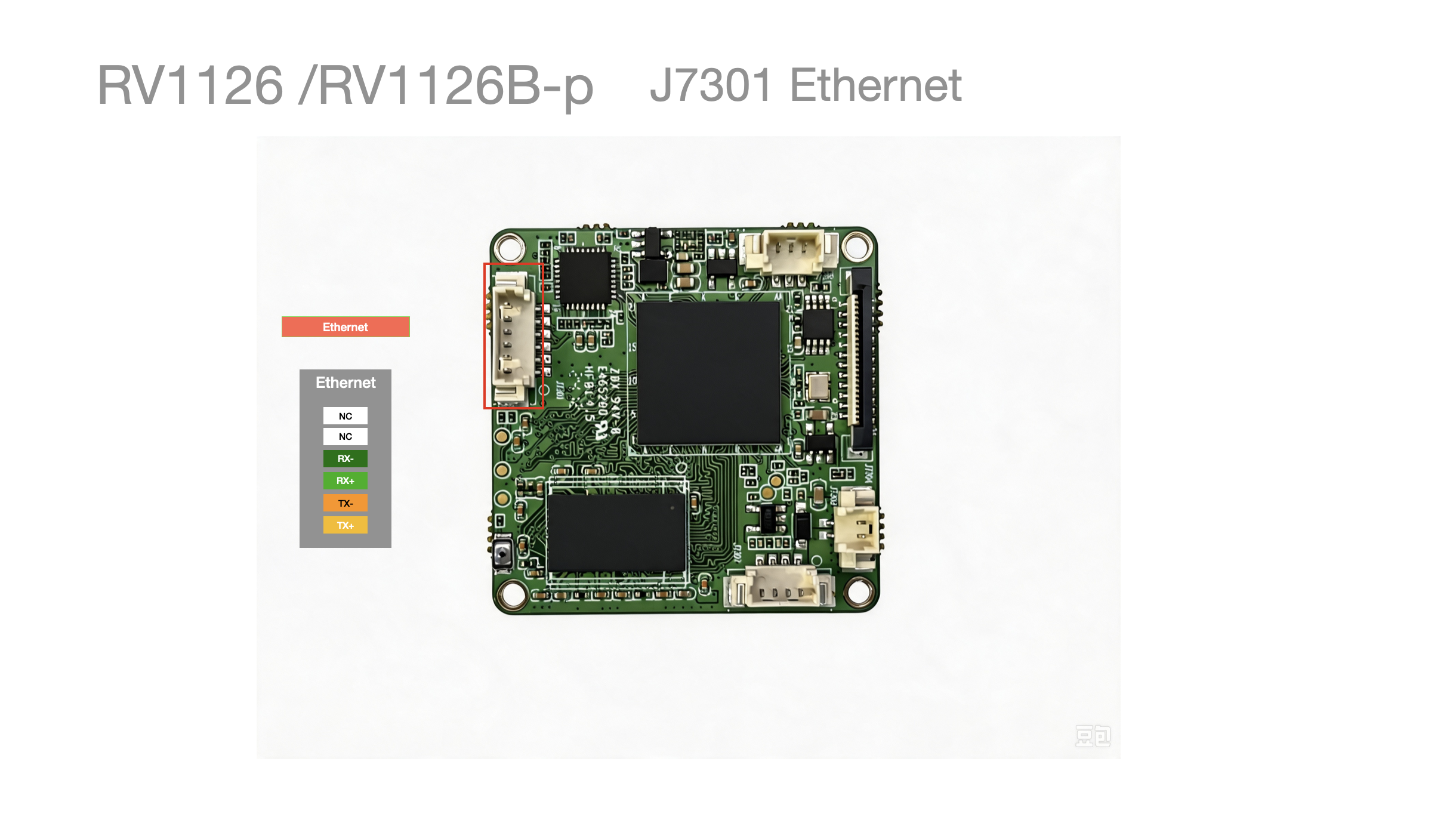
Connector type: mx1.25
- Supports 1x 100M Ethernet
Wiring method
| Pin No. | Function | Corresponding T568B | Default cable color |
|---|---|---|---|
| 1 | TX+ | 1 | Green/white |
| 2 | TX- | 2 | Green |
| 3 | RX+ | 3 | Blue/white |
| 4 | RX- | 6 | Blue |
| 5 | POE36 | Not connected (not supported) | Not connected (not supported) |
| 6 | POE12 | Not connected (not supported) | Not connected (not supported) |
RS-485 Communication Interface
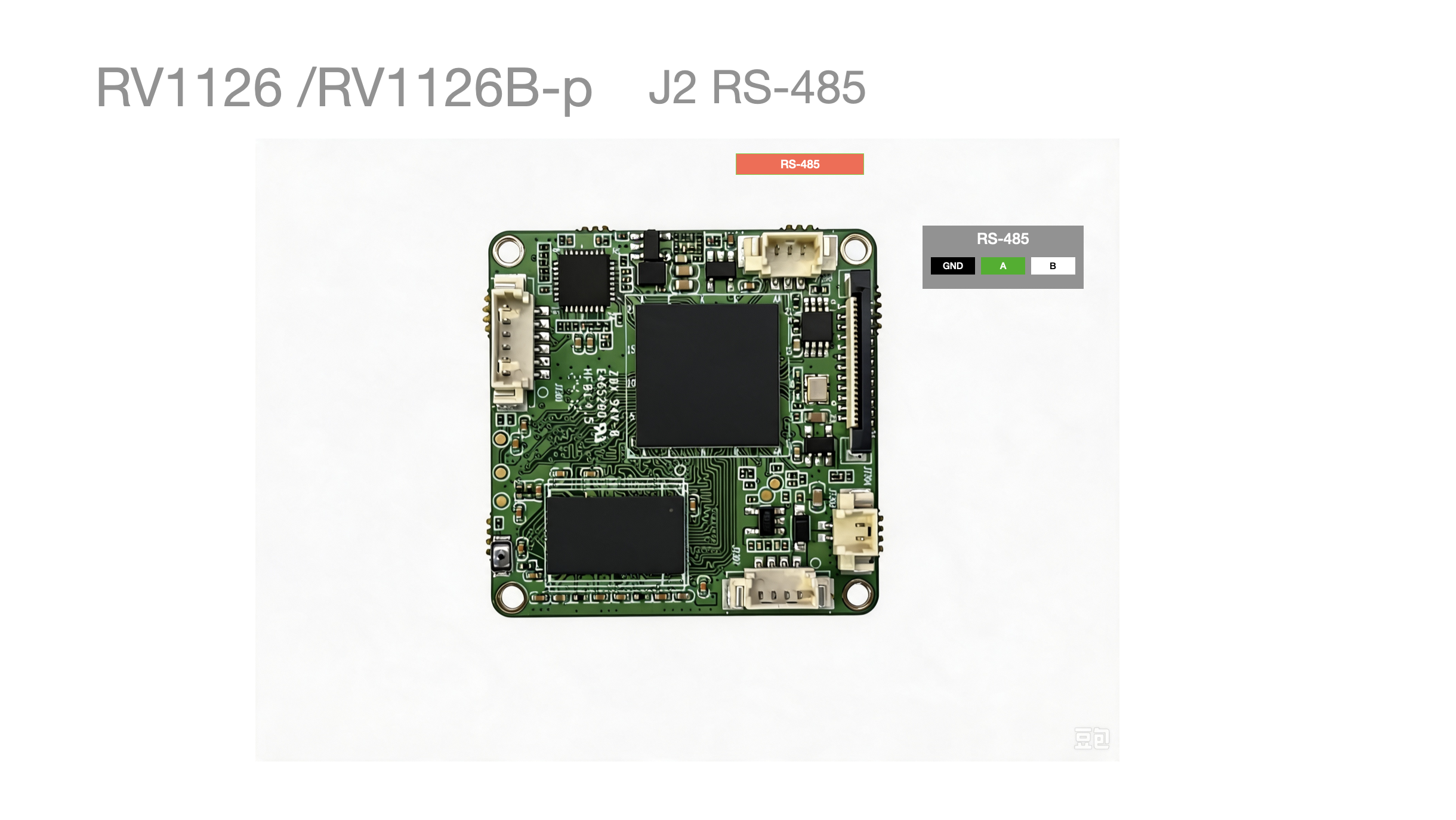
Connector type: mx1.25
The RS-485 interface is ttyS3 and the default baud rate is 9600
| Pin No. | Function |
|---|---|
| 1 | GND |
| 2 | A |
| 3 | B |
The USB-RS485 adapter shown in the figure must be purchased and configured by yourself.
Wiring method
24PIN Expansion Interface
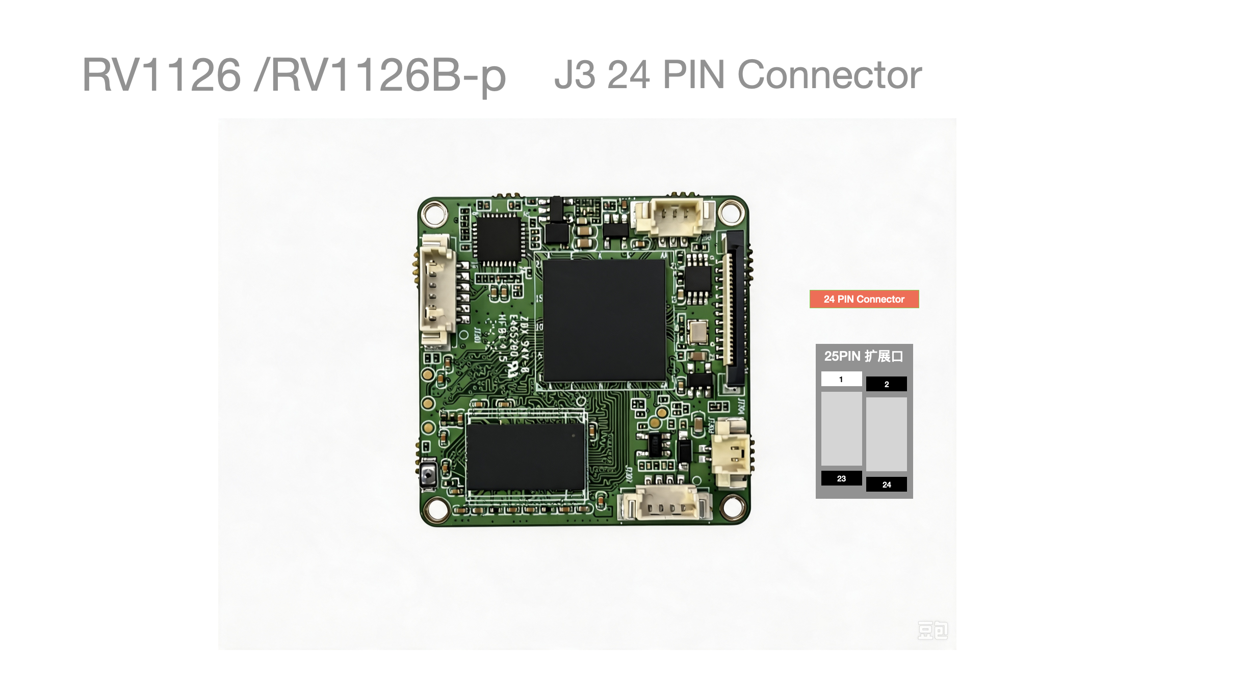
The SDIO voltage is 1.8V
The new firmware interface is ttyS2 and the default baud rate is 9600
Link: https://pan.baidu.com/s/1NyfRuSKcakxMJCZohiFl6A?pwd=fanc Extraction code: fanc Copy this content and open the Baidu Netdisk mobile app for easier operation
| Pin No. | Function | Description | Pin No. | Function | Description |
|---|---|---|---|---|---|
| 1 | GND | 13 | BT_WAKE_HOST | ||
| 2 | GND | 14 | WIFI_REG_ON | ||
| 3 | VCC5V0 | 15 | SDIO_D0 | ||
| 4 | VCC5V0 | 16 | SDIO_D1 | ||
| 5 | USB_HOST_DP | 1-6 can be used as one USB Host | 17 | SDIO_D2 | |
| 6 | USB_HOST_DM | 1-6 can be used as one USB Host | 18 | SDIO_D3 | |
| 7 | GND | 19 | SDIO_CMD | ||
| 8 | ADKEY_IN0 | 20 | SDIO_CLK | ||
| 9 | GND | 21 | UART0_RTSN | ||
| 10 | WIFI_WAKE_HOST | 22 | UART0_TX | TTL 1V8; tested and works for 3V3 TX/RX | |
| 11 | BT_RST | 23 | UART0_RX | TTL 1V8; tested and works for 3V3 TX/RX | |
| 12 | BT_WAKE | 24 | UART0_CTSN |
The USB-TTL adapter shown in the figure must be purchased and configured by yourself.
Wiring method
Appendix: 24pin expansion interface information:
24 PIN 0.5MM FPC connector, model: X05C2024TZ
Power Interface
Connector type: mx1.25
Do not connect 12V it will directly cause the device and the camera to bedamaged
Wiring method
Measured Power
- Test method:
-
Flash the default
BuildrootfirmwareRV1126_RV1109_AI_Camera_V1.1.4_20240907_imx307_imx415.img -
Power on normally, connect the network cable, and do nothing else
-
| State | Voltage | Current | Power | Remarks |
|---|---|---|---|---|
| Automatic streaming | 5.3V | 0.5A-0.6A | 2.9-3.1W | Measurement accuracy 0.1 |
USB Debug Interface
Connector type: mx1.25
-
Supports 1x USB device port for adb debugging to obtain the IP, etc.
-
Precautions - Be careful not to connect it wrongly; verify before powering on
- If the computer is equipped with a camera, pay attention to the USB power supply capability; connecting to USB 3.0 is required to achieve 5V1A power supply
- If the computer's USB port cannot supply enough power to start the device,
connect the 5V power supply first , and then connect the USB debug port
| Pin No. | Function | Default cable color |
|---|---|---|
| 1 | VCC5V0 | Red |
| 2 | OTG_DM | White |
| 3 | OTG_DP | Green/white |
| 4 | GND | Black |
MIPI-CSI Camera Interface
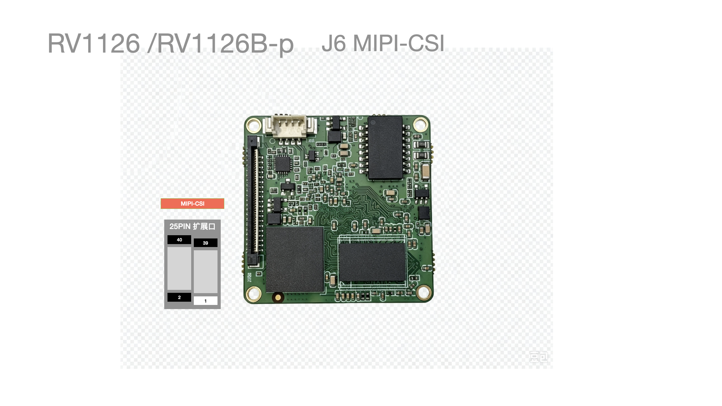
-
40PIN dual MIPI/LVDS input interface (supports 4lane)
-
See the datasheet for the interface definition
-
Default bundle:
IMX415orIMX307optional
Wiring method
Appendix: 40pin MIPI interface information:
40 PIN 0.5MM FPC connector, model: X05C2040TZ
Debug board: FPC 24PIN flexible flat cable adapter board, FFC to 2.54 straight-through, with a soldered 0.5-pitch connector PCB
Audio Input/Output Interface
Connector type: mx1.25
Defaults to maximum power; speakers of 8 ohms or more are recommended to avoid distortion
Debug Interface
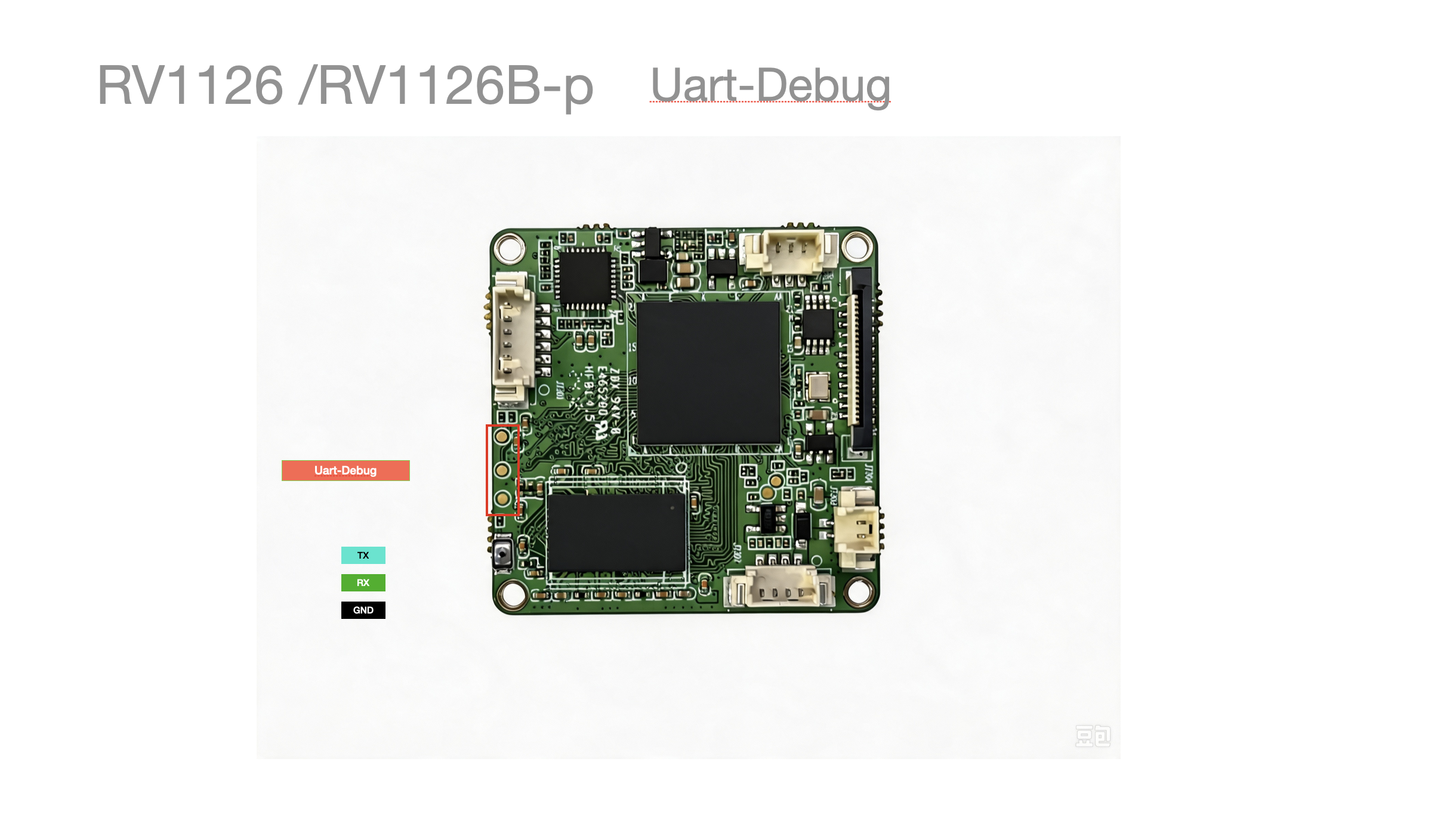
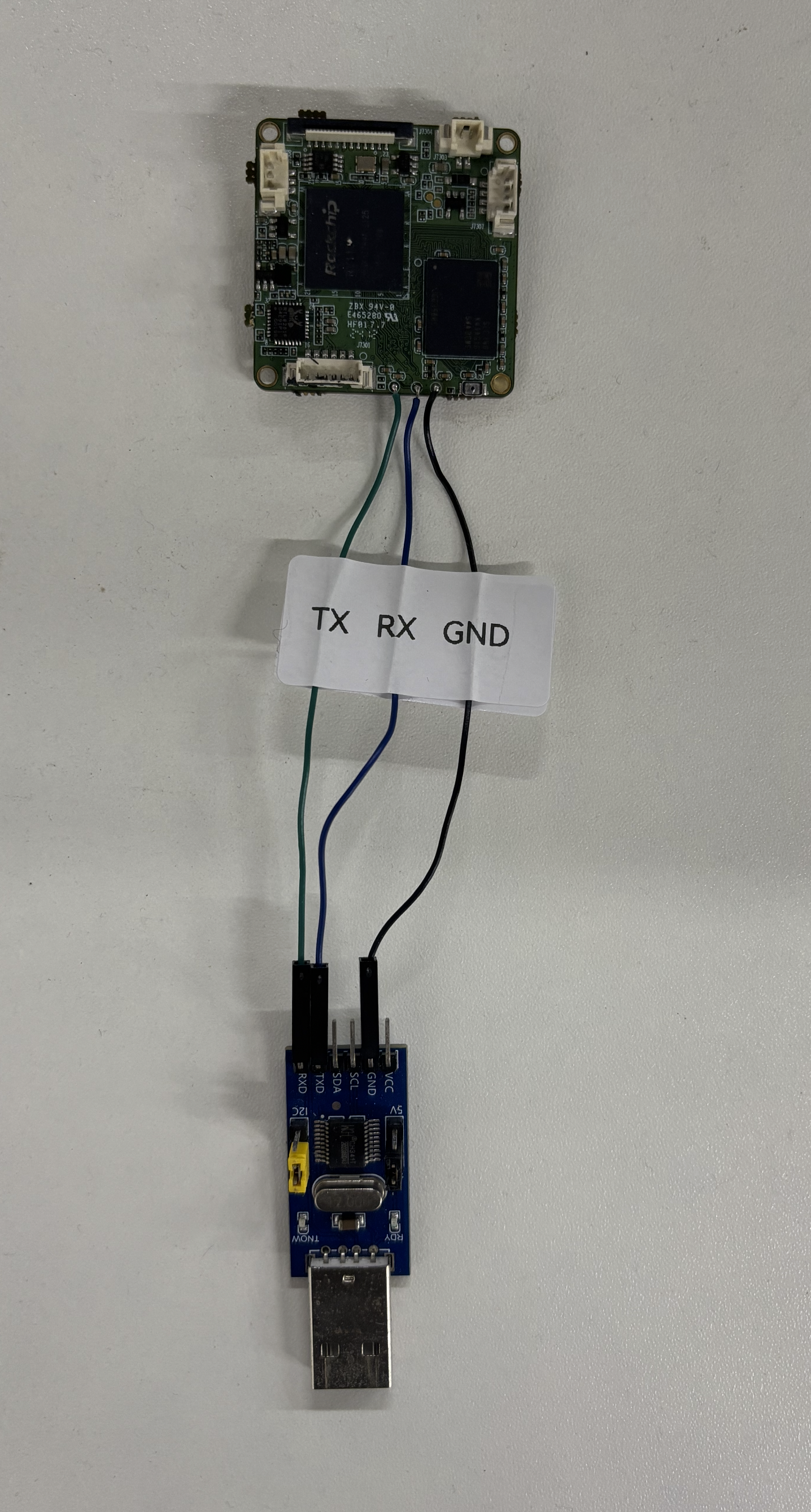
Please use TTL debug 1500000 (five 0s 0️⃣)
| Pin No. | Function |
|---|---|
| 1 | GND |
| 2 | RX |
| 3 | TX |
Usage
The USB-TTL adapter shown in the figure must be purchased and configured by yourself.
The debug pads need to be soldered by yourself.
Loader Flashing Button
Hold the Boot button and then power on (USB) to enter Loader boot mode
Maskrom Flashing Button
Hold the Maskrom button and then power on (USB) to enter Maskrom boot mode
- You can short the two contacts shown in the figure with tweezers or another metal object
Schematics
For CAM126B-P, you can refer to the CAM126 wiring