Interface Definitions

GT8550 provides a rich set of interfaces, as shown below:
Device Interface Definitions
Device interfaces
J1 TYPE-C Port: Full-featured
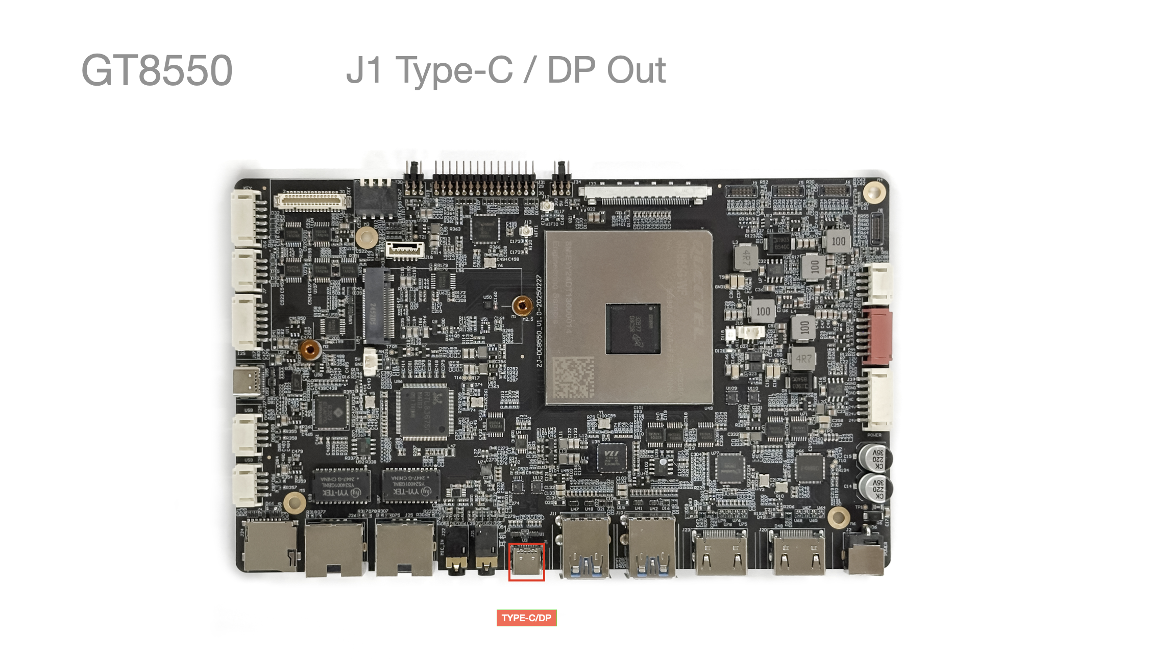
- USB 3.1 Gen2 TYPE-C x1: supports DP + data mode
J2/J3 Power
Connection method
Interface Definition
| Pin No. | Pin Description | Wire Color (Reference) | Remarks |
|---|---|---|---|
| 1 | GND | Black | Ground |
| 2 | GND | Black | Ground |
| 3 | GND | Black | Ground |
| 4 | NC | ||
| 5 | 12V | Red | Operating voltage 12-24V |
| 6 | 12V | Red | Operating voltage 12-24V |
| 7 | 12V | Red | Operating voltage 12-24V |
Just Connect a 12V Power Supply
- Supports a
DC 12-24V 4PINpower connector
Measured Power
-
Test method:
-
Flash the default
Androidfirmware -
Power on normally, unlock the screen and do nothing else
-
Only the mainboard power is measured; the backlight is not connected.
-
| Status | Voltage | Current | Power | Remarks |
|---|---|---|---|---|
| Normal boot without a screen connected | 12.16V | 0.234A | Standby 2.8576W | Measurement accuracy 0.01, |
J4 Backlight Power
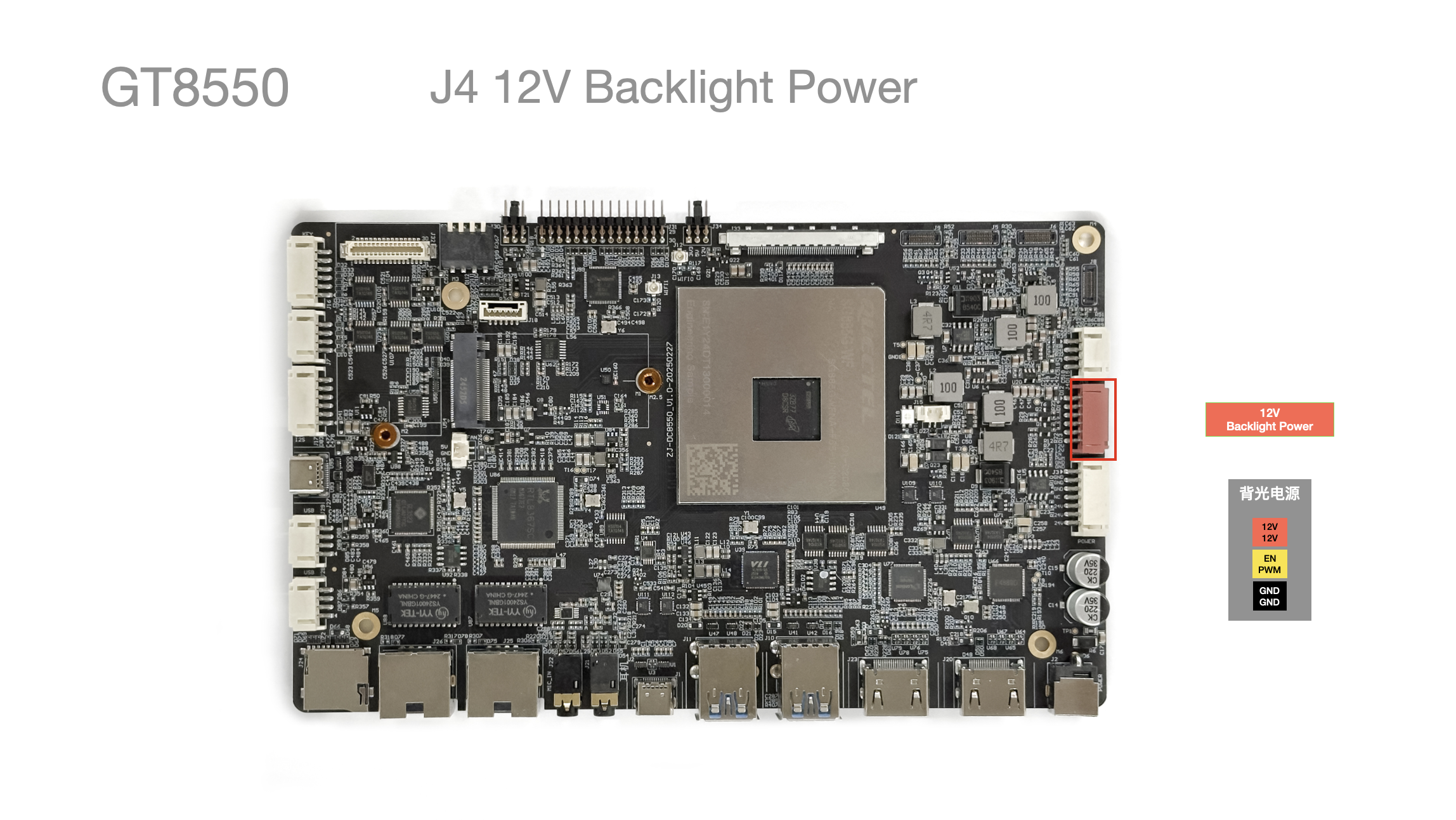
| Pin No. | Pin Description | Wire Color (Reference) | Remarks |
|---|---|---|---|
| 1 | 12V | Red | Operating voltage 12V |
| 2 | 12V | Red | Operating voltage 12V |
| 3 | BL EN | Yellow | Backlight control |
| 4 | BL PWM | Yellow | Backlight control |
| 5 | GND | Black | Ground |
| 6 | GND | Black | Ground |
- Maximum
3A Max
J5/J6/J8/J9 MIPI CSI Interfaces
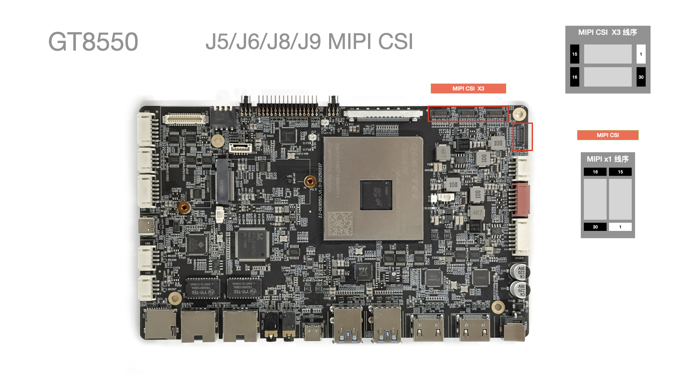
- Supports 4 MIPI CSI channels
J7 Speaker/Power Amplifier Output
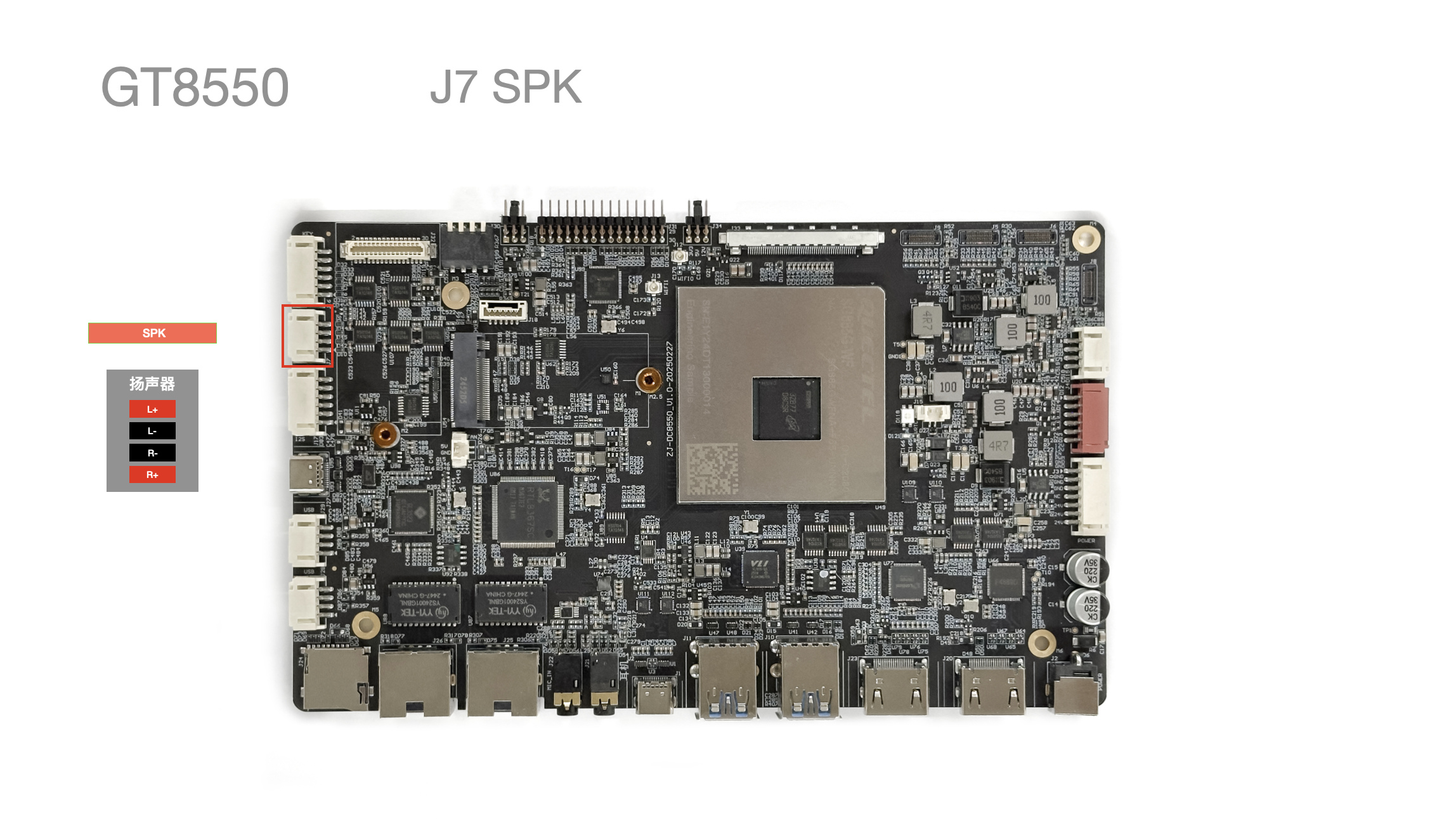
| Pin No. | Pin Description | Wire Color (Reference) |
|---|---|---|
| 1 | L+ | Red |
| 2 | L- | Black |
| 3 | R- | Black |
| 4 | R+ | Red |
J10/J11 USB - A 3.0 x4
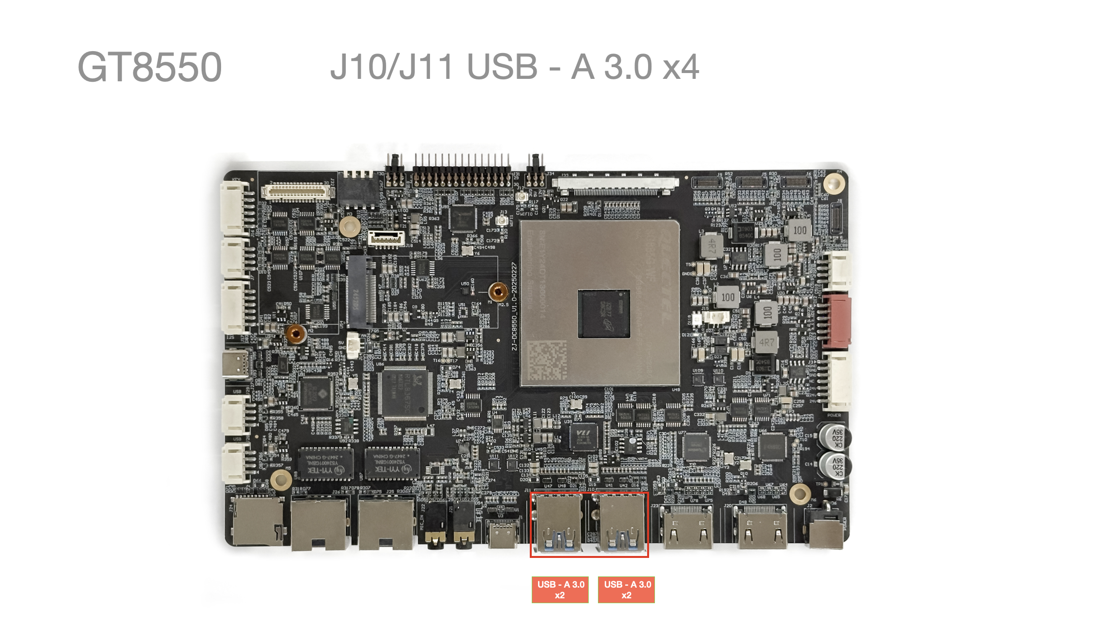
- Standard USB 3.0 Type-A
J12/J13 WI-FI Network
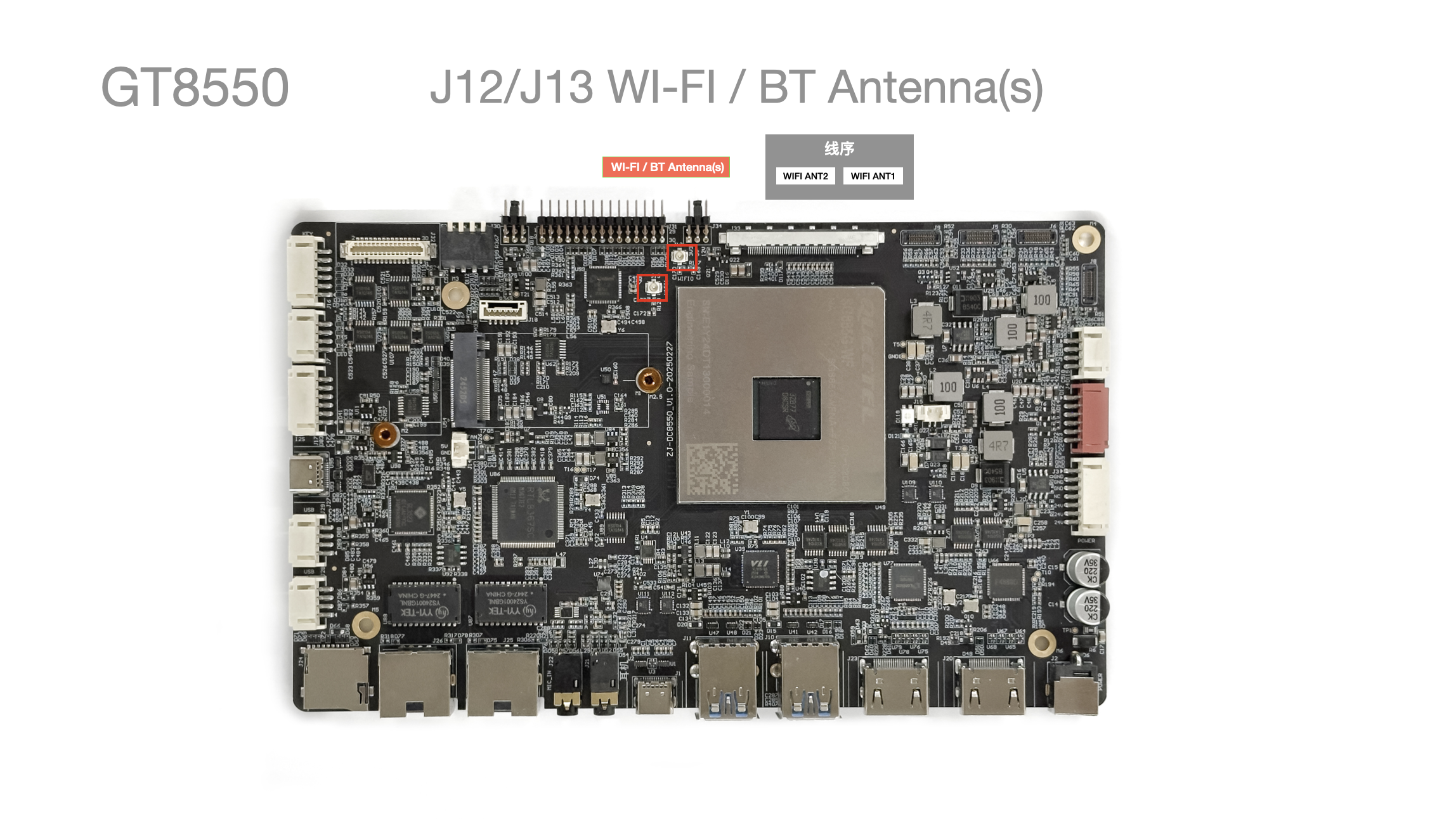
- WLAN: WiFi 7: Up to 5.8 Gbps speed, 2x2 320MHz Wi-Fi 7, XBS
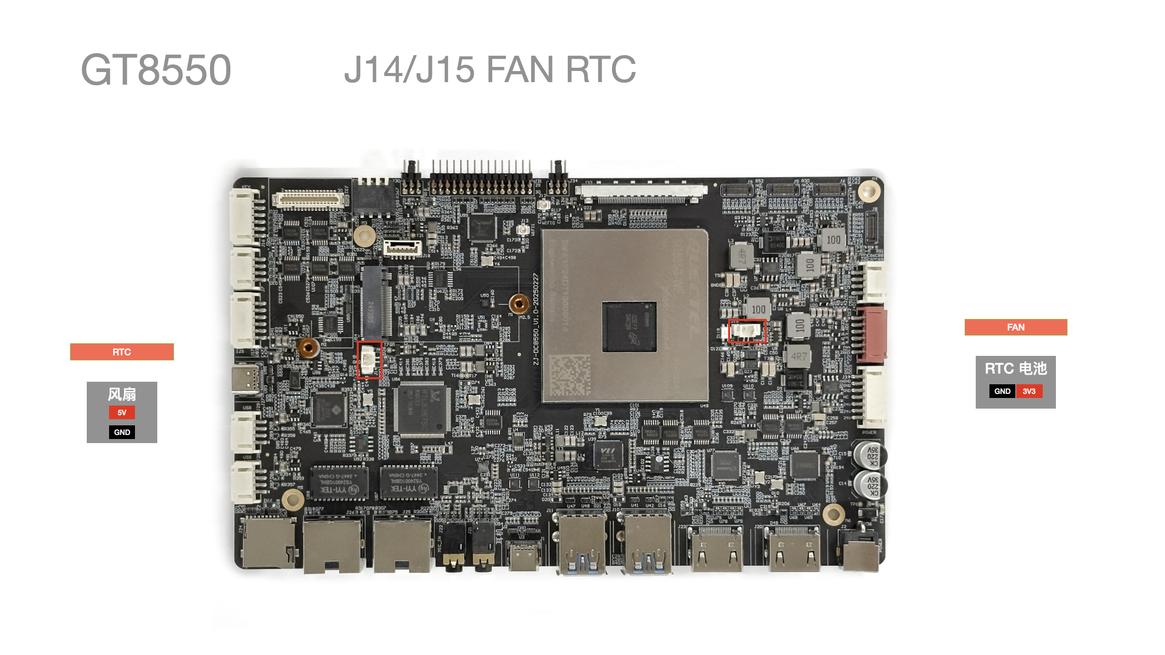
J14/J15 Fan/RTC Battery
-
PWM speed-controlled fan interface x1
-
Reserved RTC battery x1
J8 Panel Button Interface
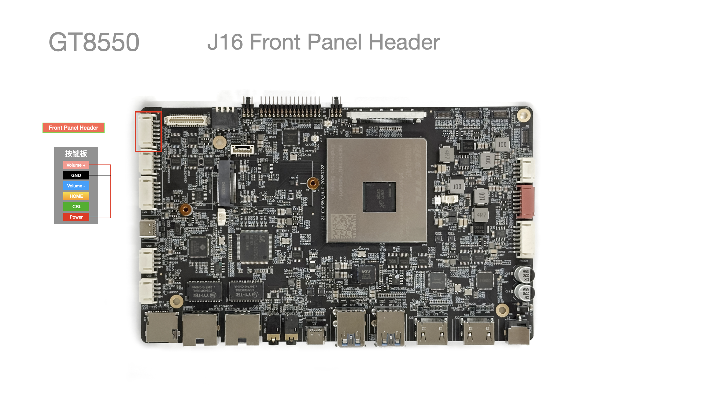
| Pin No. | Pin Description | Remarks |
|---|---|---|
| 1 | Volume + | Volume + |
| 2 | GND | Common ground |
| 3 | Volume - | Volume - |
| 4 | HOME | Home button |
| 5 | CBL | Undefined |
| 6 | Power | Power button |
J17 I2S Digital Audio
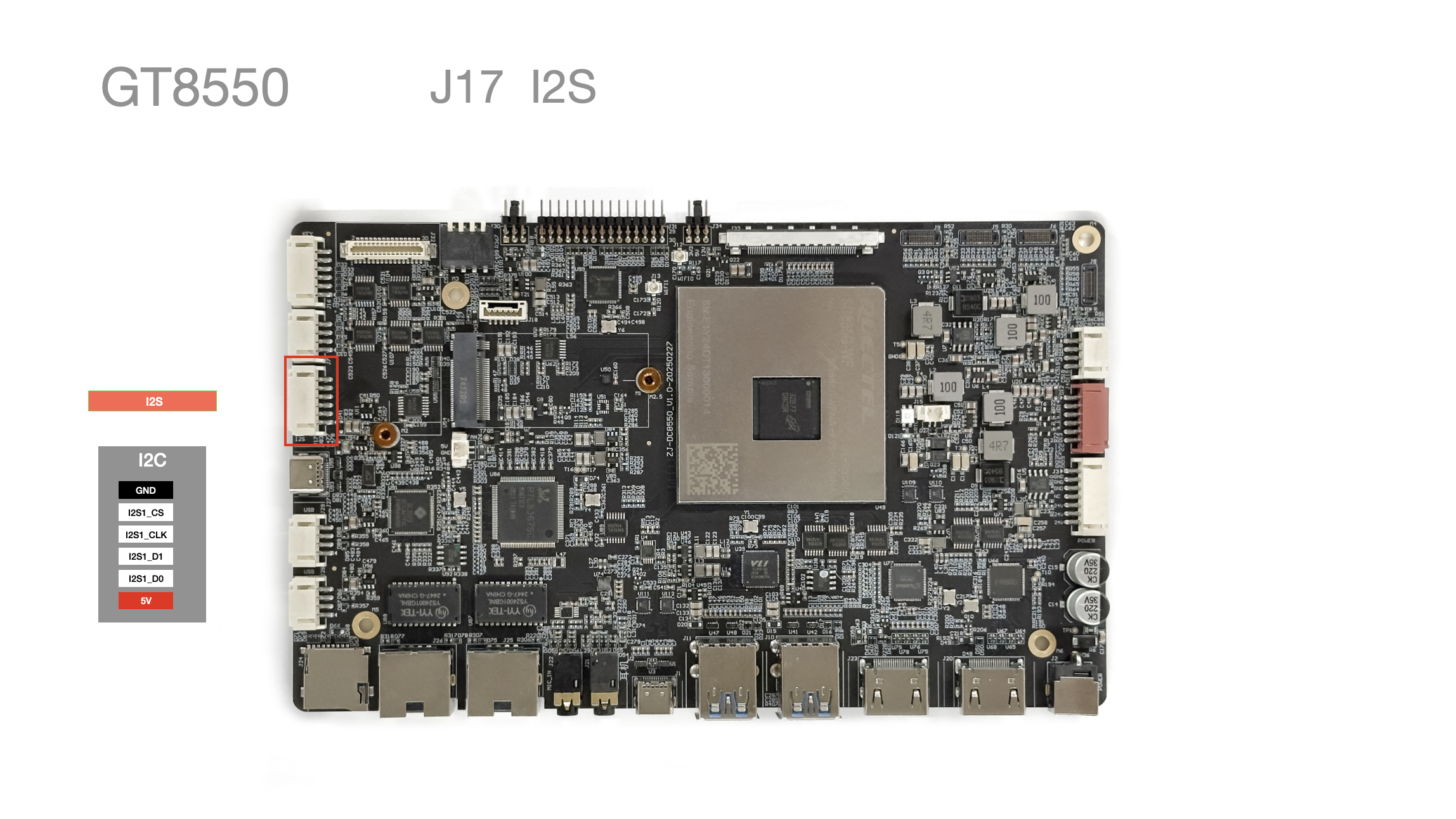
| Pin No. | Pin Description | Remarks |
|---|---|---|
| 1 | GND | |
| 2 | I2S1_CS | |
| 3 | I2S1_CLK | |
| 4 | I2S1_D1 | |
| 5 | I2S1_D0 | |
| 5V | Power |
J19 Serial Port
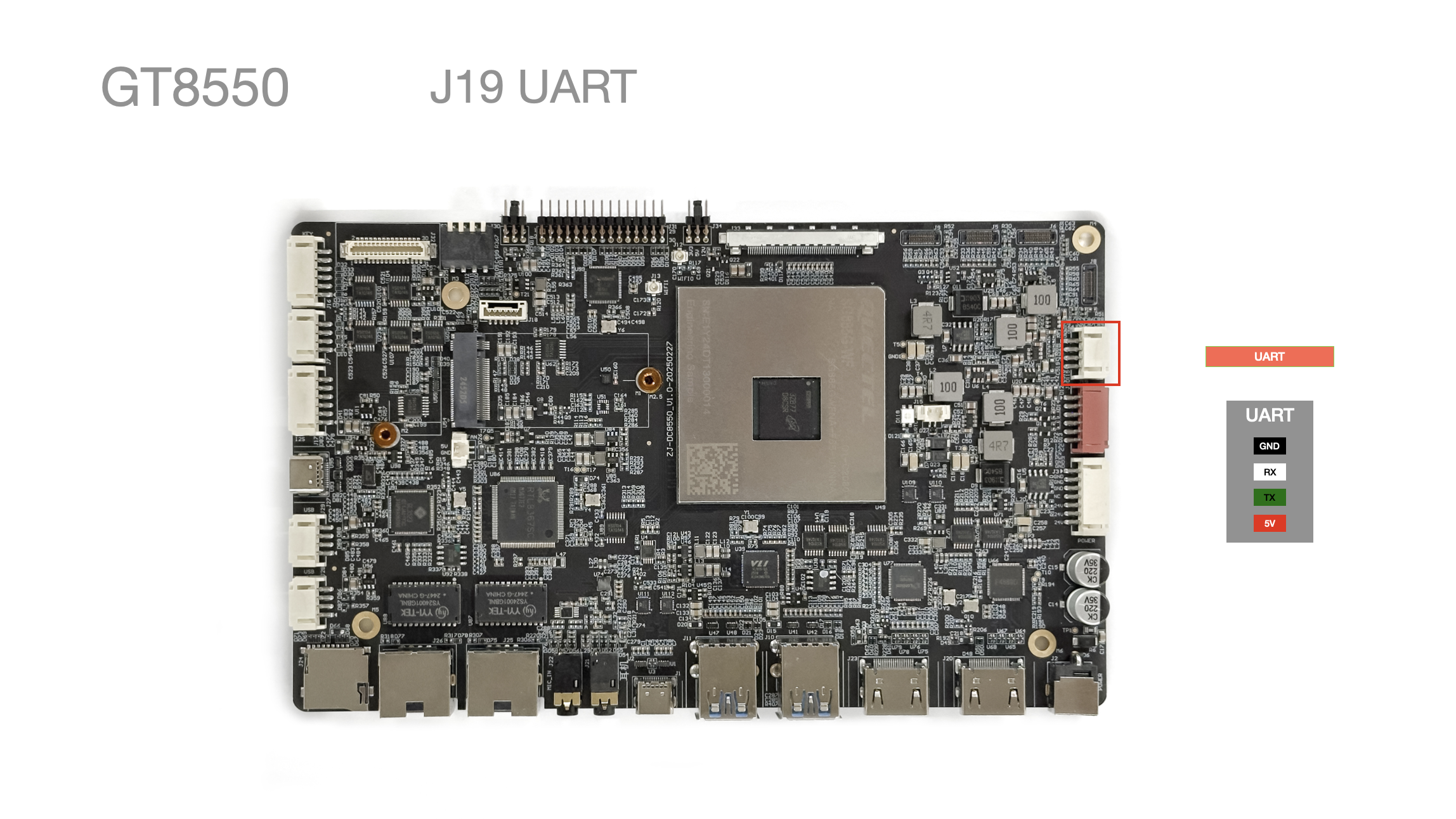
| Pin No. | Pin Description | Wire Color (Reference) |
|---|---|---|
| 1 | GND | Black |
| 2 | TX | Green |
| 3 | RX | White |
| 4 | 5V | Red |
J20/J23 HDMI-IN HDMI-OUT
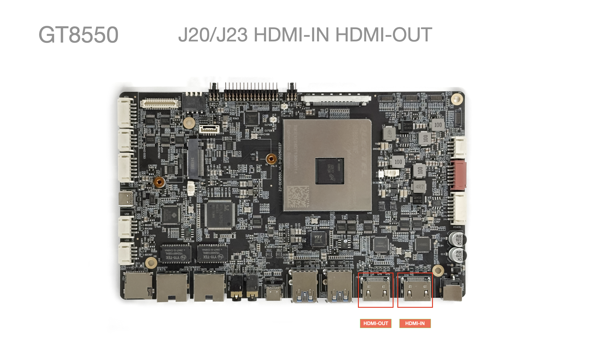
- Supports HDMI-IN
Up to 3840*2160@30fps
- Supports HDMI-OUT
Up to 3840*2160@30fps
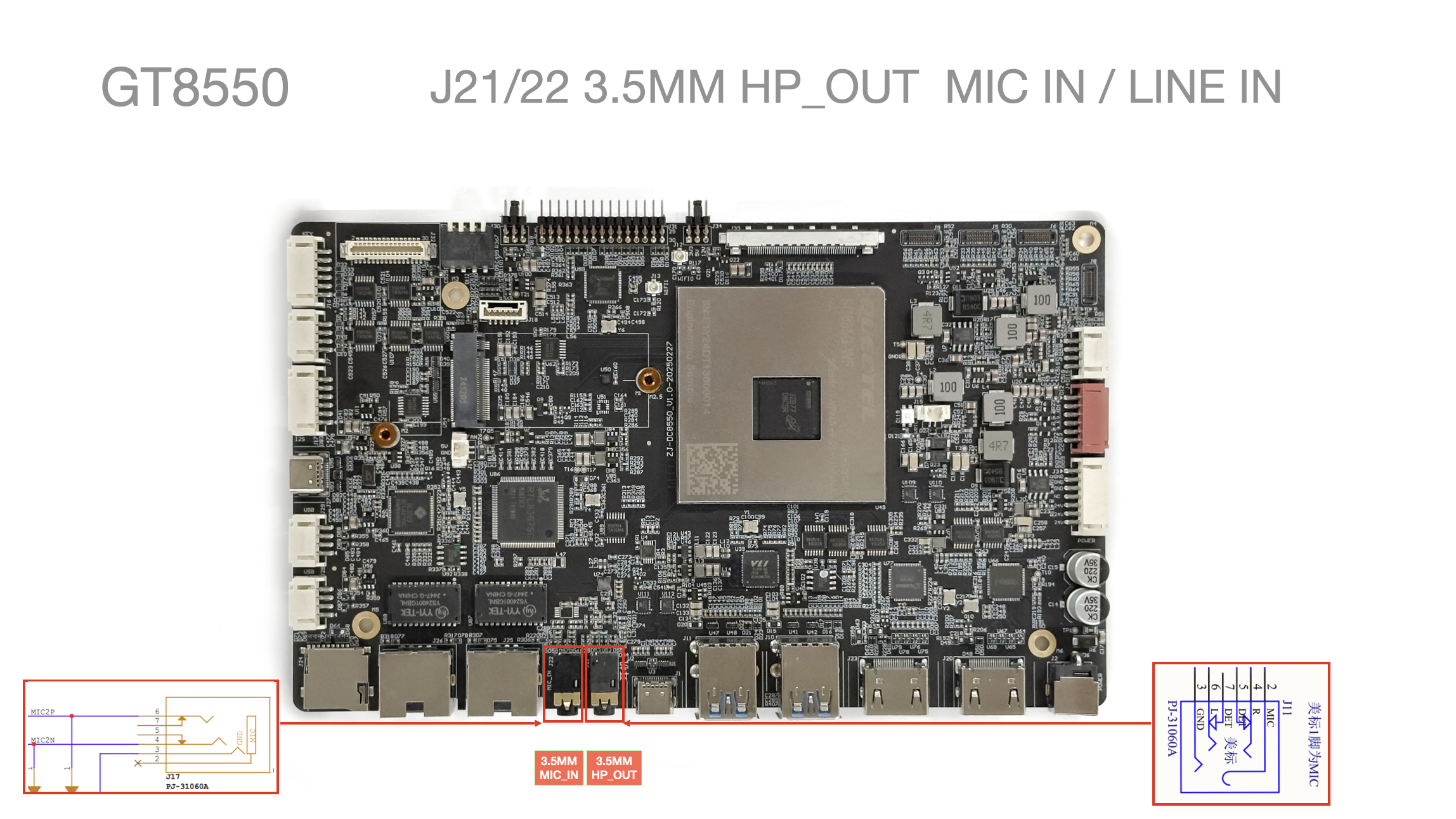
J21/J22 Headphone / Microphone Interfaces
-
Supports American-standard headphone x1
-
Supports microphone x1
J24 SD-CARD (TF-CARD)
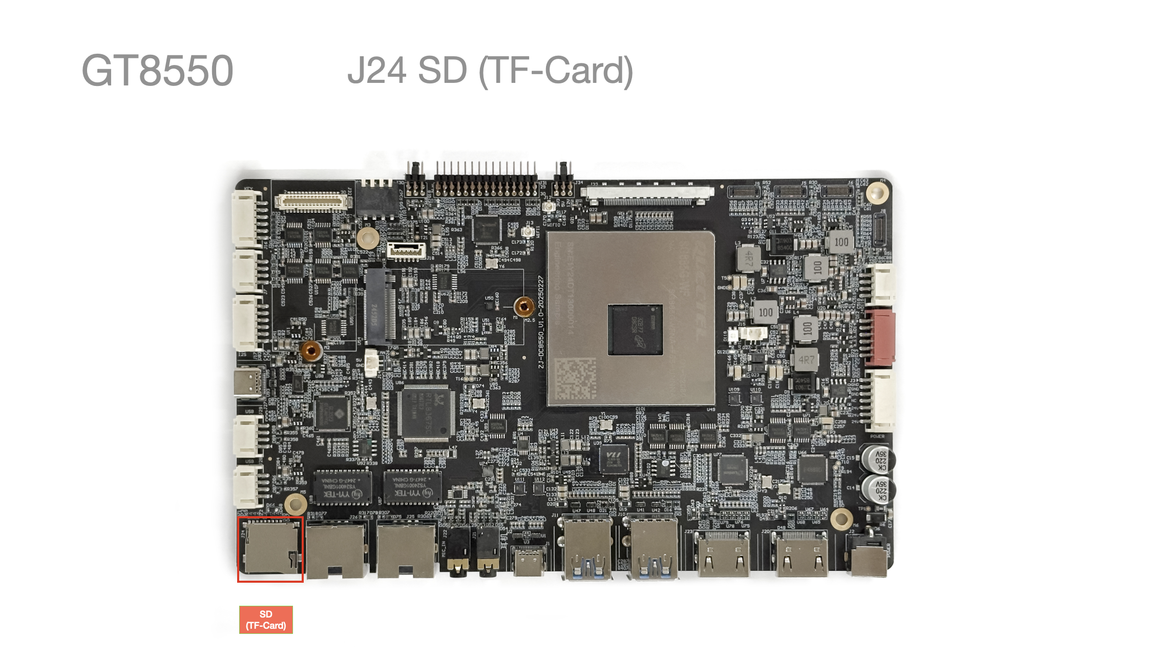
- Supports TF card x1
J25/J26 Ethernet
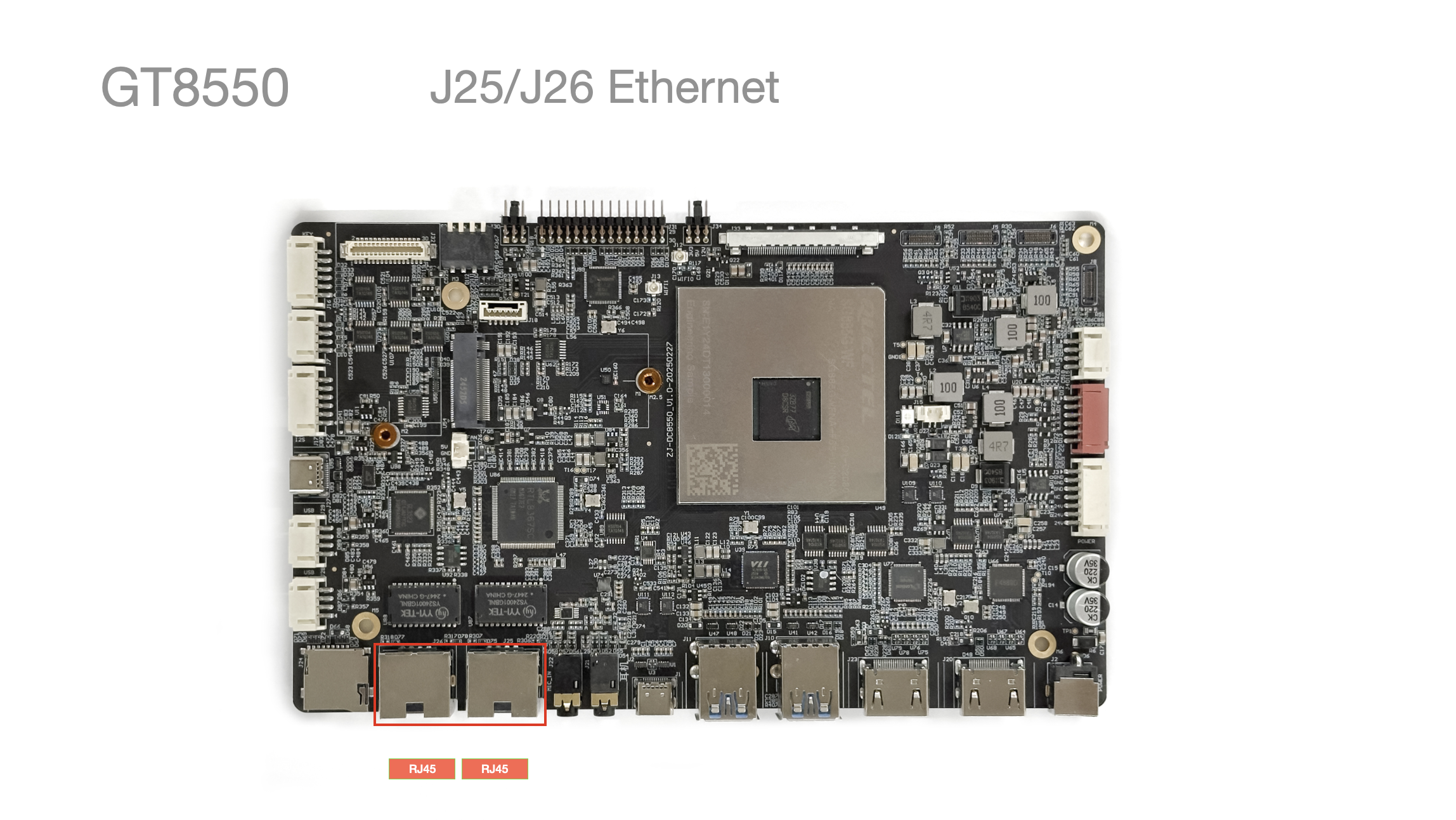
- Ethernet 1000 Mbps x2
J27 Type-C 3.0 Host
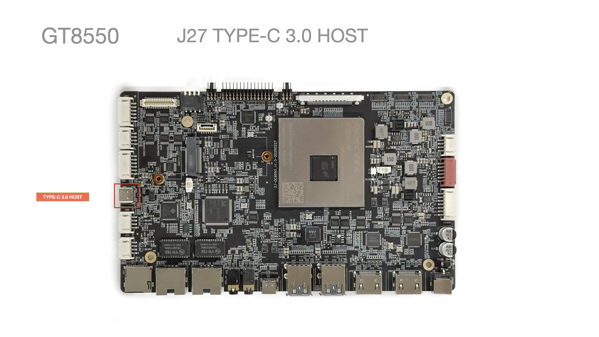
- Supports Type-C 2.0 Host x1
J28/J29 USB 2.0 Host x4
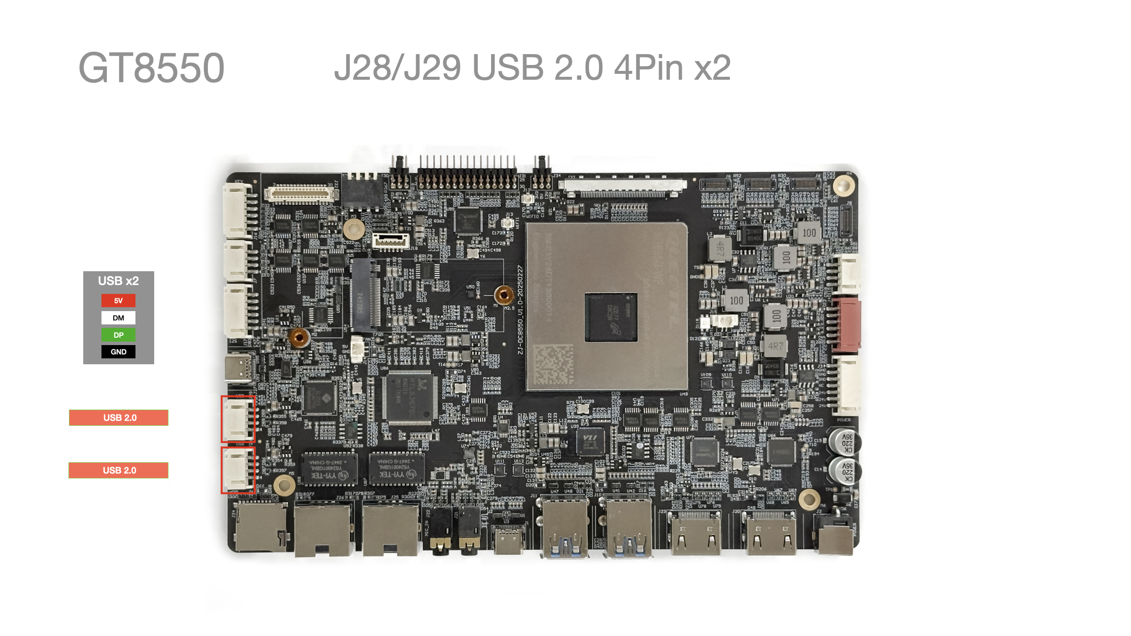
- Supports USB 2.0 Host x2
J30 LVDS Power Jumper
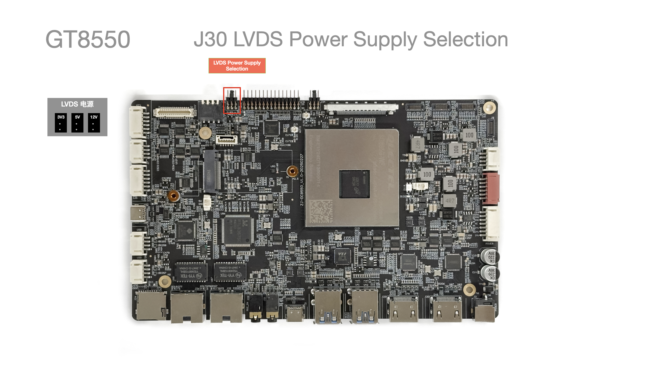
- Switches the LVDS voltage
Supports 3.3V / 5V / 12V
J31 LVDS
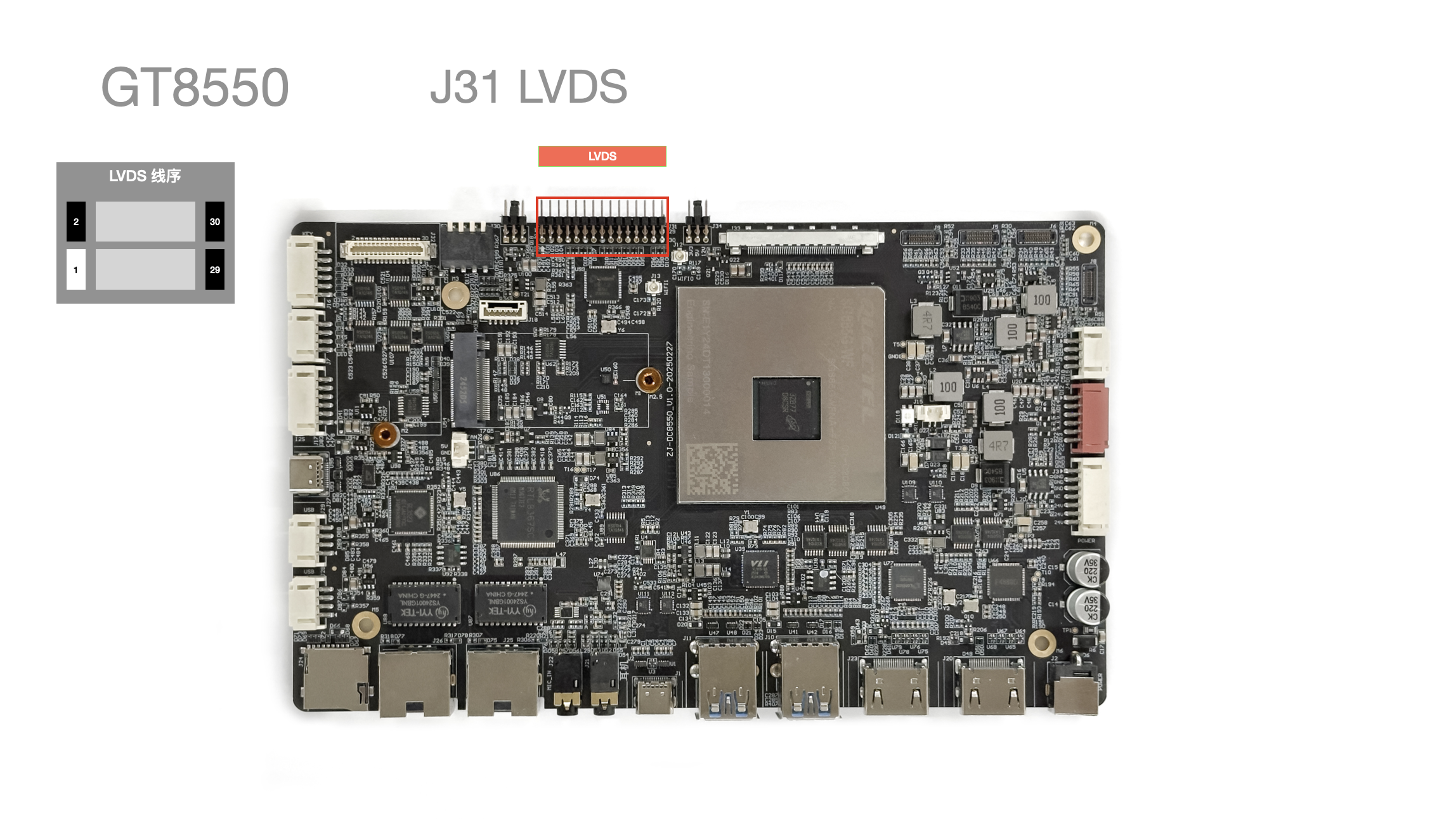
- Supports LVDS x1
Up to 1920x1080
J32 IO Expansion
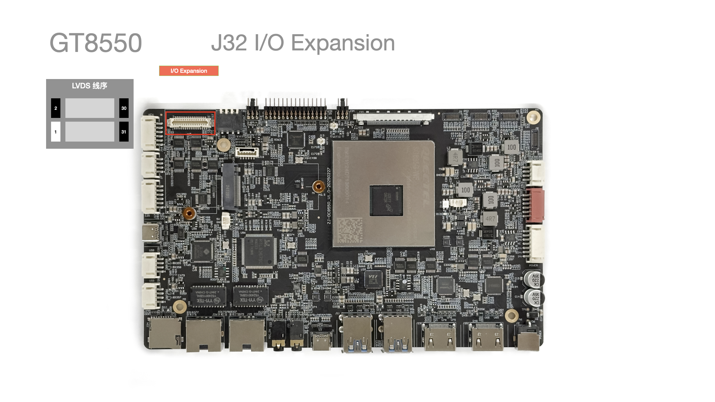
- Supports a multi-function expansion interface
| Pin No. | Pin Description | Pin No. | Pin Description |
|---|---|---|---|
| 1 | GPIO | 17 | GND |
| 2 | SPI_CLK | 18 | I2C_SDA |
| 3 | GPIO | 19 | GND |
| 4 | SPI_CS | 20 | I2C_SCL |
| 5 | GPIO | 21 | GND |
| 6 | SPI_MISO | 22 | GND |
| 7 | GPIO | 23 | GND |
| 8 | SPI_MOSI | 24 | TX |
| 9 | GND | 25 | 5V |
| 10 | GND | 26 | RX |
| 11 | GPIO | 27 | 5V |
| 12 | DBG_TXD | 28 | TX |
| 13 | GPIO | 29 | 5V |
| 14 | DBG_RSD | 30 | RX |
| 15 | GND | 31 | 5V |
| 16 | GND |
J34 EDP Power Jumper
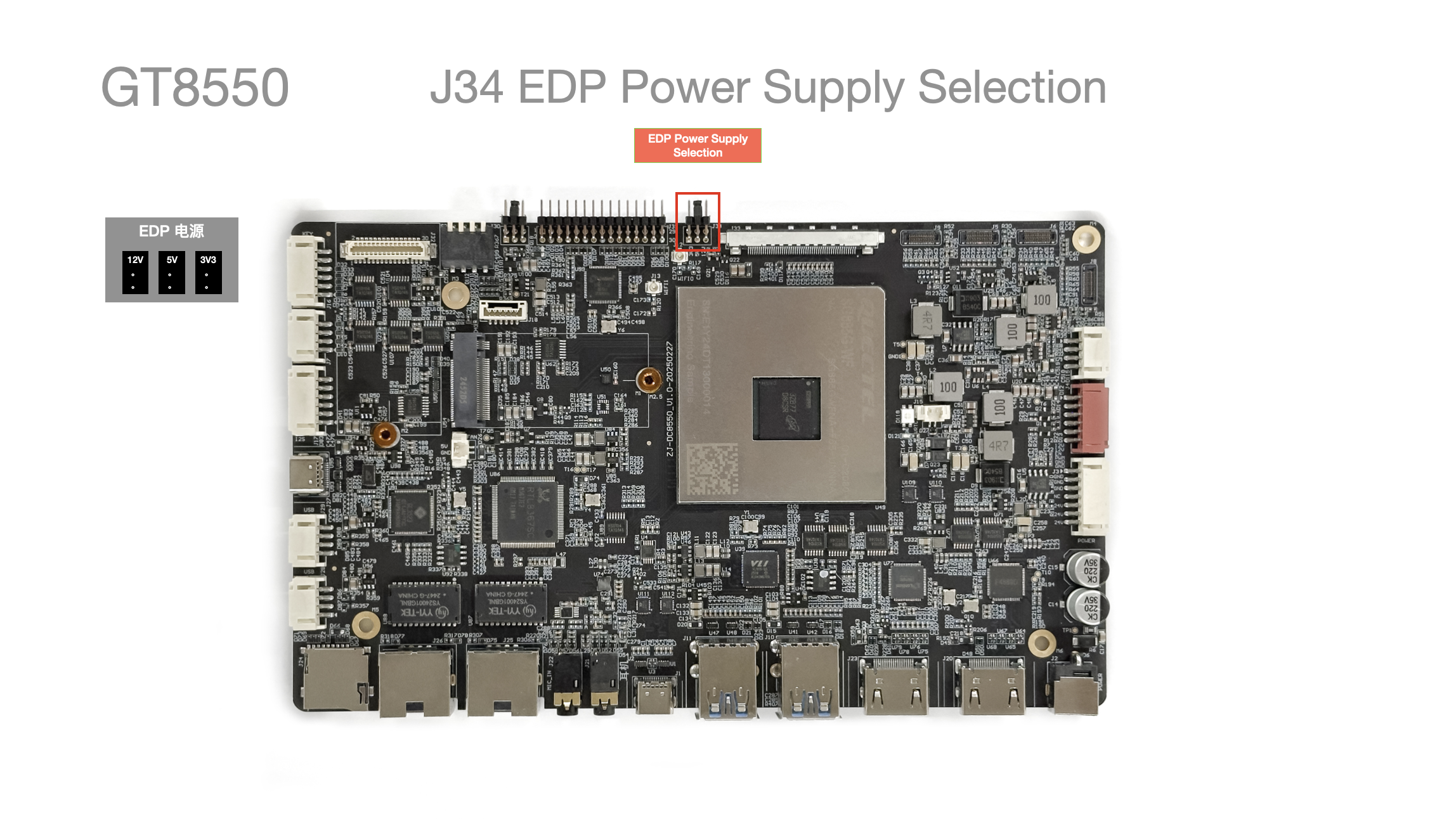
- Switches the EDP voltage
Supports 3.3V / 5V / 12V
U52 PCIE M.2 Storage Expansion
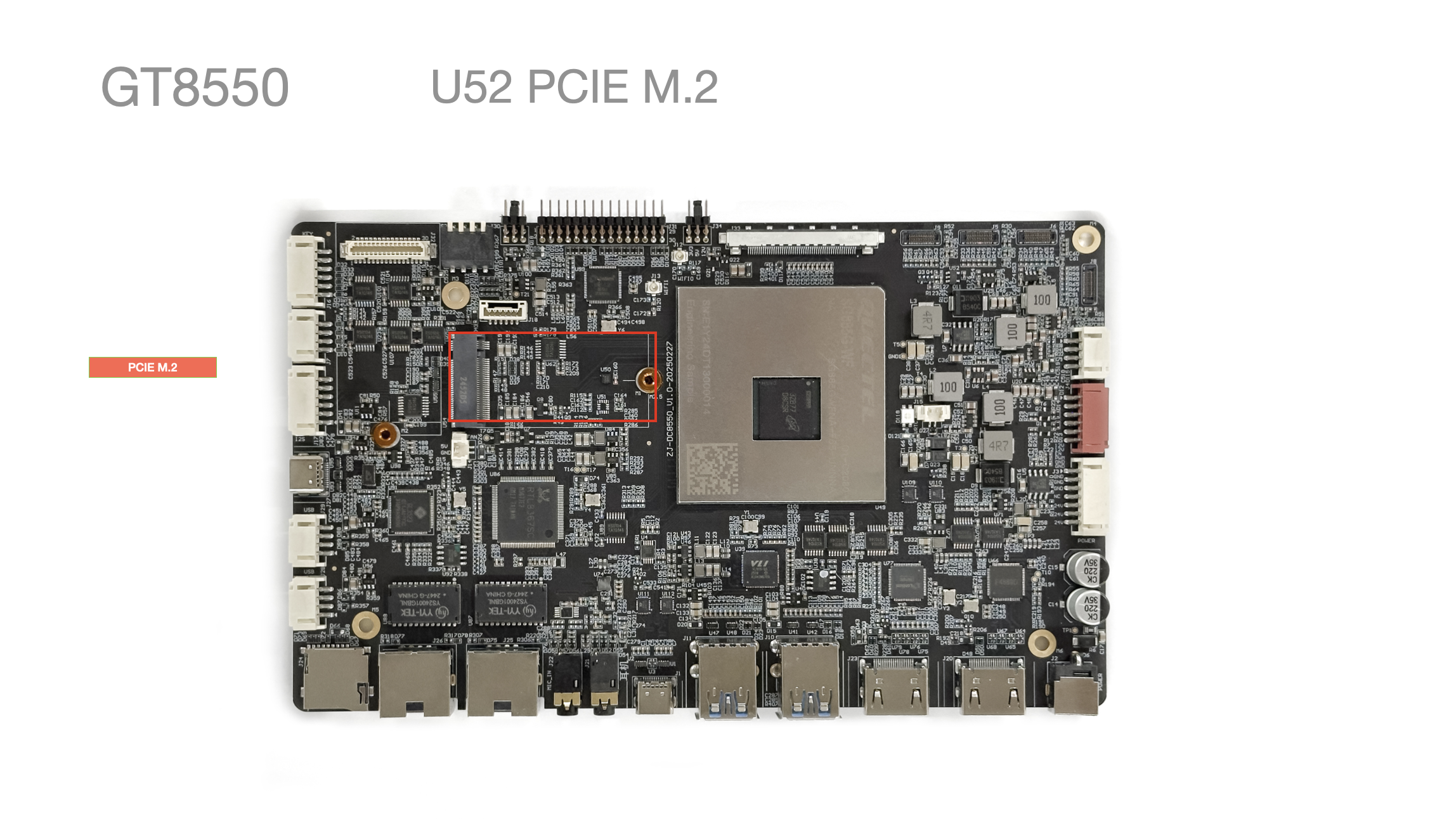
- PCIE M.2 x1:
Supports M Key 2242 NVME SSD
S1 Boot Button
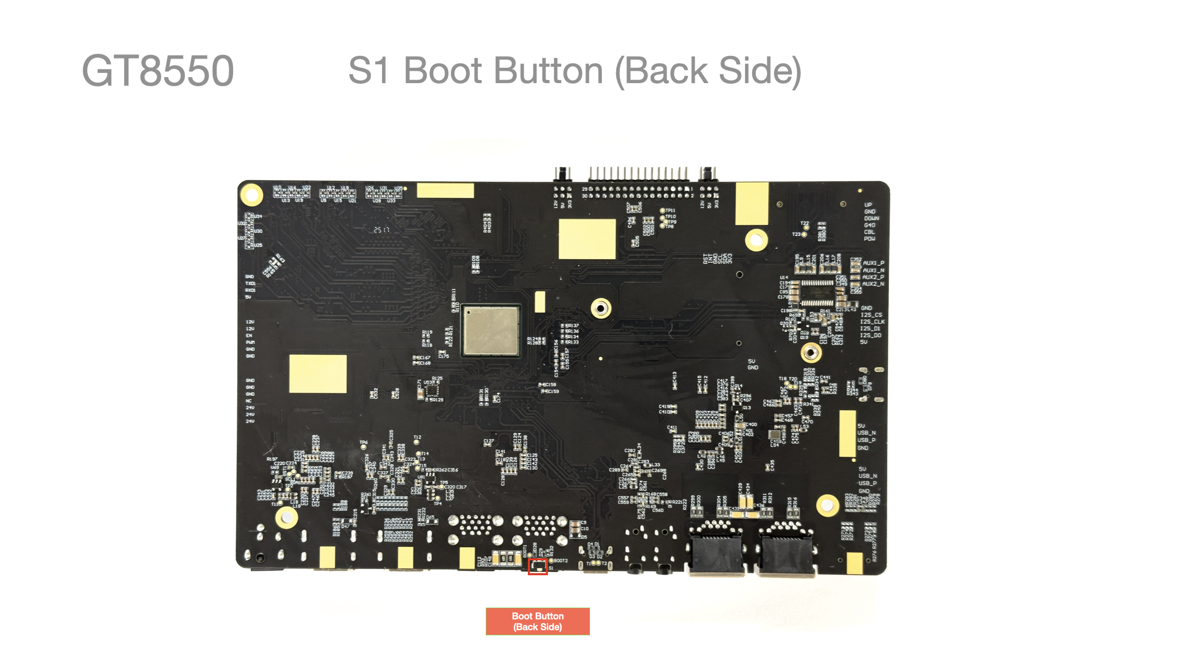
- Switches the bootloader startup mode
Used for system upgrade