Quick Install - Linux / OpenWrt

EC25-AF Installation
Quickly get started with the EC25-AF LTE Cat 4 module (Mini PCIe to USB) on Linux / OpenWrt
Prerequisites
- A Linux device (this article uses an OpenWrt / ImmortalWrt router as an example)
- EC25-AF Mini PCIe module + Mini PCIe to USB 2.0 base board
- A Nano-SIM card with Internet service
- The router's WAN port has working Internet access (for downloading drivers)
If the router is not yet online, you can download the corresponding IPK/APK packages on a computer with Internet access and install them from a USB flash drive. Router architectures differ, so look up the matching version in the OpenWrt package repository.
Connecting the Device
Installing the Nano-SIM Card
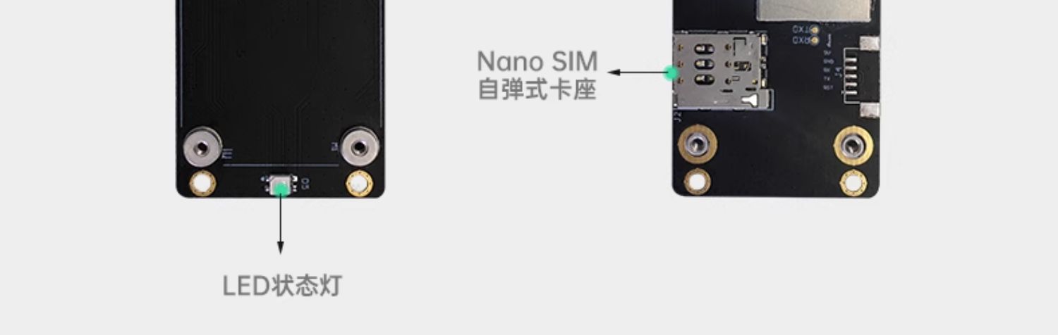
The EC25-AF has two SIM card positions:
| Card slot location | Description | Test result |
|---|---|---|
| Card slot on the module | Card holder on the Mini PCIe module PCB | AT+CPIN? → READY, IMSI / CCID readable, registration on CHN-CT normal |
| Card slot on the USB base board | Push-push card holder on the Fanconn Mini PCIe to USB base board | AT+CPIN? → READY, the same card yields identical IMSI / CCID, registration and Internet access normal |
Insert only one SIM card at a time.
SIM Slot Mapping
Test conclusions:
- Both physical card slots recognize the SIM card normally, and the IMSI and CCID read out are exactly the same
- The (U)SIM interface of the EC25-AF is specified as ×1, and the firmware does not support
AT+QUIMSLOT/AT+QCFG="simslot"(both returnERROR) - Therefore the USB base board slot and the module slot map to the same SIM path (SIM1); they are two parallel/alternative physical card holders, and there is no independently switchable SIM2 channel
Do not treat the base board slot as an independent "SIM 2". The EC25-AF(D) has only one USIM path; inserting cards into both holders at the same time causes conflicts, so insert only one.
Connecting to the Router USB Port
Plug the Mini PCIe to USB base board into the router's USB-A port.
Note: Some routers cannot supply enough power over USB. A USB hub with an independent power supply is recommended to prevent the module from rebooting repeatedly.
Configuring the Dongle - Router Side
Connecting to the Router
ssh root@192.168.1.1
The management address depends on the actual router.
Checking the USB Device
First confirm that the system has detected the module:
root@OpenWrt:~# lsusb
You should see the Quectel device (the EC25 and EC20 share the same USB PID, shown as EC25 LTE modem):
Bus 001 Device 002: ID 2c7c:0125 Quectel Wireless Solutions Co., Ltd. EC25 LTE modem
The
iProductstring oflsusbdirectly shows the module model; for example, this device reportsEC25-AF.
If lsusb: not found is reported, install usbutils first:
# OpenWrt 24.10 and earlier
opkg update
opkg install usbutils

# Versions using apk, such as ImmortalWrt 25.12
apk update
apk add usbutils
Installing Drivers and Tools
Installing the USB serial driver (for AT commands):
# opkg
opkg update
opkg install kmod-usb-serial-option

# apk
apk update
apk add kmod-usb-serial-option
Installing the ECM network adapter driver (for usb0 connectivity):
# opkg
opkg install kmod-usb-net-cdc-ether

# apk
apk add kmod-usb-net-cdc-ether
Installing the serial terminal tool:
# opkg
opkg install minicom

# apk
apk add minicom
Checking the Serial Ports
root@OpenWrt:~# ls /dev/ttyUSB*
Expected output:
/dev/ttyUSB0 /dev/ttyUSB1 /dev/ttyUSB2 /dev/ttyUSB3
The AT command port of the EC25 is usually
/dev/ttyUSB2; the baud rate measured on this device is115200.Note: After replugging the module, the AT port may become
/dev/ttyUSB3(this happened during retesting on this device). If you are not sure, sendATIto each of/dev/ttyUSB0through/dev/ttyUSB3; the one that returnsQuectelis the AT port.If
/dev/ttyUSB*does not exist, confirm thatkmod-usb-serial-optionis installed and replug the module.
Optional: Factory Reset
A reset clears the historical configuration in the module (APN, USB mode, band lock, etc.). It is recommended for new devices or when the configuration is in disarray; if the module is currently working properly, you can skip this section and go directly to Setting the USB Operating Mode.
1. Enter the AT Terminal
minicom -D /dev/ttyUSB2 -b 115200
Send AT; a reply of OK means communication is working:
AT
OK
2. Restore Factory Settings and Reboot
AT&F
OK

AT+QPRTPARA=3
OK

AT+CFUN=1,1
OK
AT+CFUN=1,1reboots the module; USB re-enumerates and the serial ports disappear briefly for 30~60 seconds.
3. Exit minicom
Press Ctrl + A, then X, and select Yes.
- After the reset,
usbnetreturns to the module default of0(QMI / RMNET); follow the next section to set ECM mode again. - After the reset the APN is cleared (the APN for
cid=1inAT+CGDCONT?is empty) and must be reconfigured, otherwiseusb0gets an IP address but has no Internet access.
Setting the USB Operating Mode
Open the AT terminal again:
minicom -D /dev/ttyUSB2 -b 115200
Checking the Current Mode
AT+QCFG="usbnet"
+QCFG: "usbnet",0
OK
Mode Description
| Parameter | Mode | Description |
|---|---|---|
| 0 | QMI / RMNET | Requires kmod-usb-net-qmi-wwan + uqmi; the EC25 factory default |
| 1 | ECM | Natively supported by Linux/OpenWrt; recommended |
| 2 | MBIM | Requires kmod-usb-net-cdc-mbim + umbim |
| 3 | RNDIS | Requires kmod-usb-net-rndis |
If the queried value is
0(default) or3(RNDIS) and the corresponding driver is not installed, you will see the module detected but no network adapter.
Switching to ECM Mode
AT+QCFG="usbnet",1
OK

AT+CFUN=1,1
OK
Wait for the module to reboot (about 30~60 seconds), then exit minicom.
Configuring the APN
After a reset the APN is empty and must be set according to the carrier (example: China Telecom ctnet):
AT+CGDCONT=1,"IPV4V6","ctnet"
OK

AT+CFUN=1,1
The APN is provided by the carrier, for example
cmnet(China Mobile),ctnet(China Telecom),3gnet(China Unicom).In ECM mode the module dials automatically using the APN for
cid=1.
Confirming the Network Adapter
root@OpenWrt:~# ls /sys/class/net
The USB ECM adapter is usually named usb0 (if eth0/eth1 are not taken, it may also be named eth2; refer to the actual output).
root@OpenWrt:~# ip addr show usb0
Expected output (the IP is assigned automatically by the module):
12: usb0: <BROADCAST,MULTICAST,UP,LOWER_UP> mtu 1500 state UP qlen 1000
    link/ether 72:c0:2e:c6:5f:18 brd ff:ff:ff:ff:ff:ff
    inet 192.168.225.51/24 brd 192.168.225.255 scope global usb0
Unlike the BG95, the EC25 still exposes the AT serial ports after switching to ECM mode (/dev/ttyUSB0 ~ /dev/ttyUSB3),
so you can use minicom to query CSQ, CEREG and other statuses while online.
Configuring Internet Access
Option 1: Command Line (UCI)
Change the WAN port device to usb0 (the interface names depend on your setup; this article uses wan / wan6):
uci set network.wan.device='usb0'
uci set network.wan6.device='usb0'

uci commit network
service network reload
In a multi-WAN environment (for example, wan1 as the primary link and wan3 as the cellular backup), it is recommended to set a higher metric on the cellular interface to enable failover:
uci set network.wan3.device='usb0'
uci set network.wan36.device='usb0'
uci set network.wan3.metric='20'
uci set network.wan36.metric='20'

uci commit network
service network reload
The smaller the metric value, the higher the priority. Keep
wan1at the default0and set cellular to20, so the wired link is preferred and cellular is the backup; unplugging the network cable switches over automatically.
Option 2: Web Interface
- Open
Network→Interfaces→wan→Edit - Select
usb0as theDevice - Click
Save→Save & Apply - For IPv6, apply the same settings to
wan6
Verification
Checking the Interface Status
root@OpenWrt:~# ifstatus wan
Confirm "up": true and that a 192.168.225.x address has been obtained.
Checking the Routes
root@OpenWrt:~# ip route
default via 10.0.0.1 dev eth1  src 10.0.0.43
default via 192.168.225.1 dev usb0  src 192.168.225.51  metric 20
Testing the Module Link
root@OpenWrt:~# ping -c 3 192.168.225.1
If this succeeds, the ECM link between the router and the module is working.
Testing on a Specific Adapter (verify cellular without unplugging the cable)
root@OpenWrt:~# ping -I usb0 -c 3 223.5.5.5
64 bytes from 223.5.5.5: seq=0 ttl=50 time=56.7 ms
64 bytes from 223.5.5.5: seq=1 ttl=50 time=32.9 ms
64 bytes from 223.5.5.5: seq=2 ttl=50 time=30.2 ms
IPv6 Test
In a multi-WAN environment the IPv6 default route carries a source address prefix, so the source address must be specified for testing:
root@OpenWrt:~# ip -6 addr show usb0
root@OpenWrt:~# ping -6 -I <IPv6 address of usb0> -c 3 2400:3200::1
Tested on ImmortalWrt 25.12.2 (MT7981, kernel 6.12):
- Module model
EC25-AF(D), firmwareEC25AFFDR07A08M4G_01.002.01.002 - The SIM was recognized normally whether inserted in the card slot on the module or the card slot on the USB base board:
+CPIN: READY, identical IMSI / CCID, successful registration onCHN-CT - The two card slots map to the same USIM path (SIM1); there is no independent SIM2
- After a factory reset the default
usbnetvalue is0; after switching to1(ECM),usb0was created - In ECM mode
/dev/ttyUSB0~/dev/ttyUSB3remain available (the AT port may bettyUSB2orttyUSB3) - After a factory reset the APN is empty; after configuring
ctnetand rebooting, both IPv4 and IPv6 worked normally
FAQ
| Symptom | Cause | Solution |
|---|---|---|
lsusb does not show 2c7c:0125 | USB not enumerated / insufficient power | Use another USB port or a powered hub |
lsusb shows it, but no /dev/ttyUSB* | Serial driver not installed | Install kmod-usb-serial-option |
No usb0 | usbnet=0/3 but no QMI/RNDIS driver installed | Switch to ECM (usbnet=1) or install the corresponding driver |
usb0 has no IP | DHCP client not running | Confirm the interface proto is dhcp and reload the network |
usb0 has an IP but no Internet access | APN is empty after the reset | Run AT+CGDCONT=1,"IPV4V6","<APN>" and reboot the module |
| No AT response | Wrong serial port or baud rate | Confirm /dev/ttyUSB2 and baud rate 115200 (you may also try 9600) |
+CSQ: 99,99 persists for a long time after a reset | The module is searching for a network again | Wait 1~2 minutes and use AT+QENG="servingcell" to confirm the cell it has camped on |
| Abnormal behavior when cards are inserted in both slots | Both slots share one USIM path | Insert only one card; see SIM Slot Mapping |
For more AT commands, refer to Device Debugging.