General FAQ RV1126 (B-p)

General FAQ RV1126(B-p)
Cannot Power On / Cannot Stream / Flashing Tool Not Recognized / Flashing Failed
Try reflashing the firmware first! Try reflashing the firmware first! Try reflashing the firmware first!
- The system may have crashed
- The software may have crashed
- The boot / Mask button was not held to enter flashing mode
- The firmware does not match the hardware
Note that RV1126 / CAM126B-P are not compatible with each other; the chips are different
You can try the following two ways to enter flashing mode and reflash
RV1126
CAM126B-P
Loader Mode Button
Hold the Boot button and then power on (USB) to enter Loader boot mode
Maskrom Mode Button
Hold the Maskrom button and then power on (USB) to enter Maskrom boot mode
- You can use tweezers or another metal object to short the two contacts shown in the figure
Video Latency! Special Note!
Players such as VLC will have
On Windows, use EasyPlayer to reduce latency
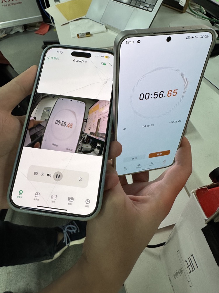
- Reference latency
200ms
On the left, an
iPhoneconnected to the LAN routervia Wi-Fiuses theIPCamssoftware within the LAN to monitor the actual latency of the CAM126B-P for comparison
Lens Thread Information
Lens thread: m12 P0.5
What Is the Operating Temperature? At What Temperature Does It Throttle, and At What Temperature Does It Shut Down?
Our mainboard is designed for -30-65 -22°F-149°F with humidity below 90. The chip datasheet's ambient temperature range is wider than the mainboard's; the SDK does not throttle by temperature—it performs a software shutdown at 115°C and a hardware reset at 120°C.
The device tree of the RV1126B-P, rv1126bp.dtsi, includes #include "rv1126b.dtsi" on line 6; the thermal protection points are all defined in the following file, and the board-level dts does not modify them:
rv1126b_linux6.1_sdk_v1.1.0/kernel/arch/arm64/boot/dts/rockchip/rv1126b.dtsi
| Item | Temperature | Description | Source |
|---|---|---|---|
| Mainboard design temperature | -30°C~65°C (-22°F~149°F), humidity below 90 | Whole-device specification; operate within this range | Product specification |
| Chip ambient operating temperature Ta | -20°C~85°C, typical 25°C | Recommended chip operating ambient temperature | RV1126B-P Datasheet Rev 1.2 (2025-09), Table 3-2 Recommended operating condition |
| Chip storage temperature Tstg | -40°C~125°C | Absolute rating, not an operating temperature | Same as above, Table 3-1 Absolute ratings |
| Chip maximum junction temperature Tj | 125°C | The datasheet states Max Conjunction Temperature; Section 4.1 requires the junction temperature to stay below 125°C | Same as above, Table 3-1 and Chapter 4.1 Overview |
| On-chip temperature sensor TS-ADC | -40°C~125°C, accuracy ±3.5°C | Only the measurement range. The high-temperature alarm and system reset temperatures are described as configurable, without specific values | Same as above, Table 3-14 Electrical Characteristics for TSADC; Temperature Sensor (TS-ADC) in Features |
| Low-temperature voltage boost | Below 10°C, hysteresis 5°C | Boosts the minimum voltage below 10°C; it is neither throttling nor shutdown | rv1126b.dtsi CPU lines 341–342; DDR lines 609–610; encoder lines 3342–3343; NPU lines 3513–3514. Properties rockchip,low-temp = <10000>, rockchip,temp-hysteresis = <5000> |
| Throttling | None | There is no passive thermal trip point and no rockchip,temp-freq-table. Only the previous generation RV1126 had 75°C / 85°C frequency limiting | rv1126b.dtsi lines 1047–1055; cpu-thermal contains only the critical entry below |
| Software shutdown | 115°C, hysteresis 2°C | type = "critical"; the kernel shuts down when it reaches this point | rv1126b.dtsi lines 1048–1053, temperature = <115000>, hysteresis = <2000> |
| Hardware reset | 120°C | rockchip,hw-tshut-mode = <0>, which uses a CRU reset rather than pulling a GPIO to notify the PMIC to cut power | rv1126b.dtsi lines 2096–2098, rockchip,hw-tshut-temp = <120000> |
In the driver kernel/drivers/thermal/rockchip_thermal.c, the default tshut_temp for RV1126B is 95°C (around line 1869); the 120°C on line 2096 of the device tree overrides it, so 120°C takes effect in practice.
Network Environment! No Router
Some users do not have a router, only Wi-Fi. You can refer to the following to share the network and then connect.
- First open Control Panel
Adapter Settings
Control Panel - Network Connections - Change adapter settings
- Enable sharing
WLAN - Right-click - Properties - Sharing - Allow other network users to connect through this computer's Internet connection (N) - OK
If there are multiple Ethernet adapters, under Allow other network users to connect through this computer's Internet connection (N)
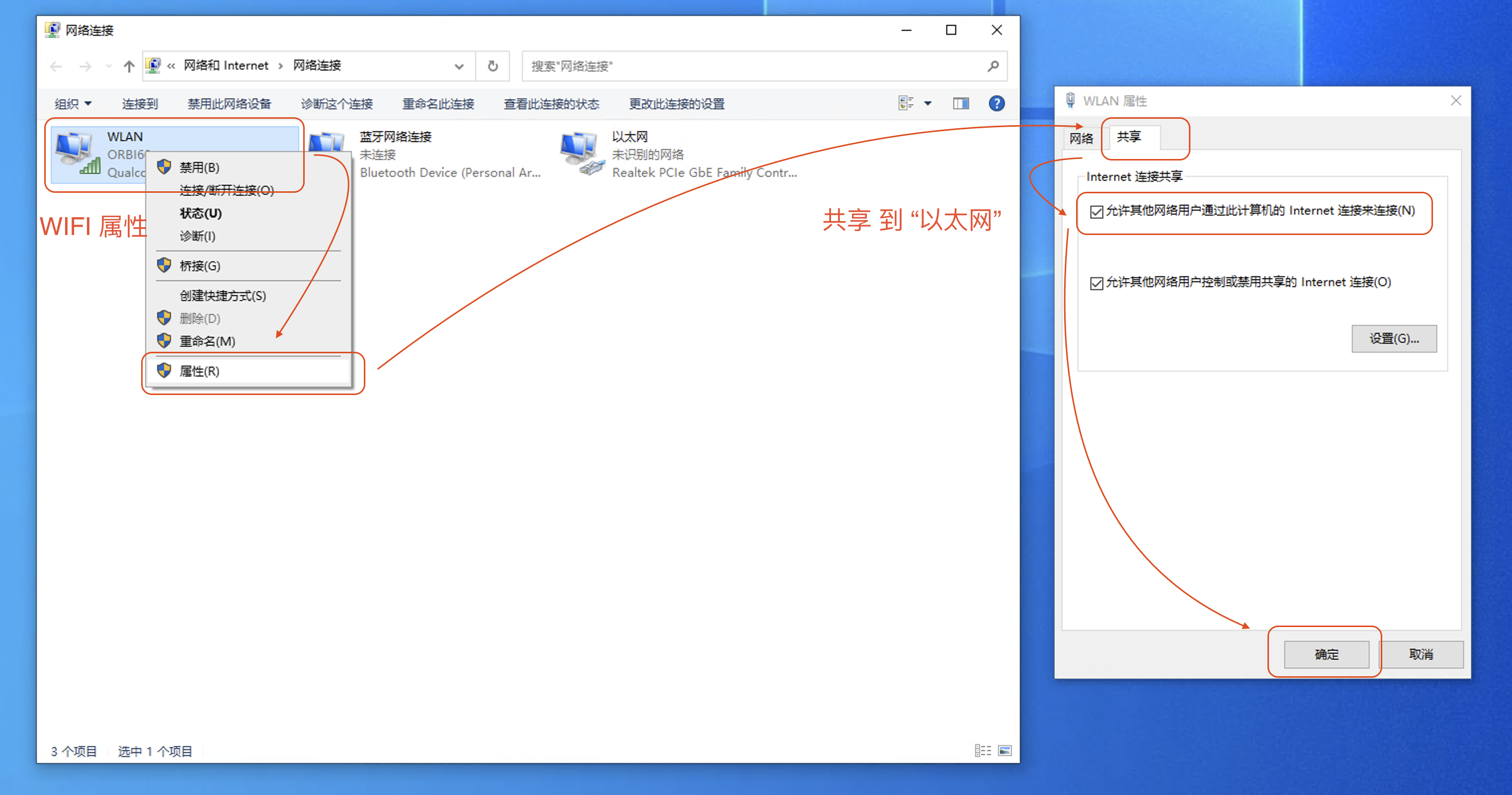
- Confirm it is enabled;
Ethernetautomatically switches to theshared subnet
Ethernet - Status - Details - 192.168.137.1
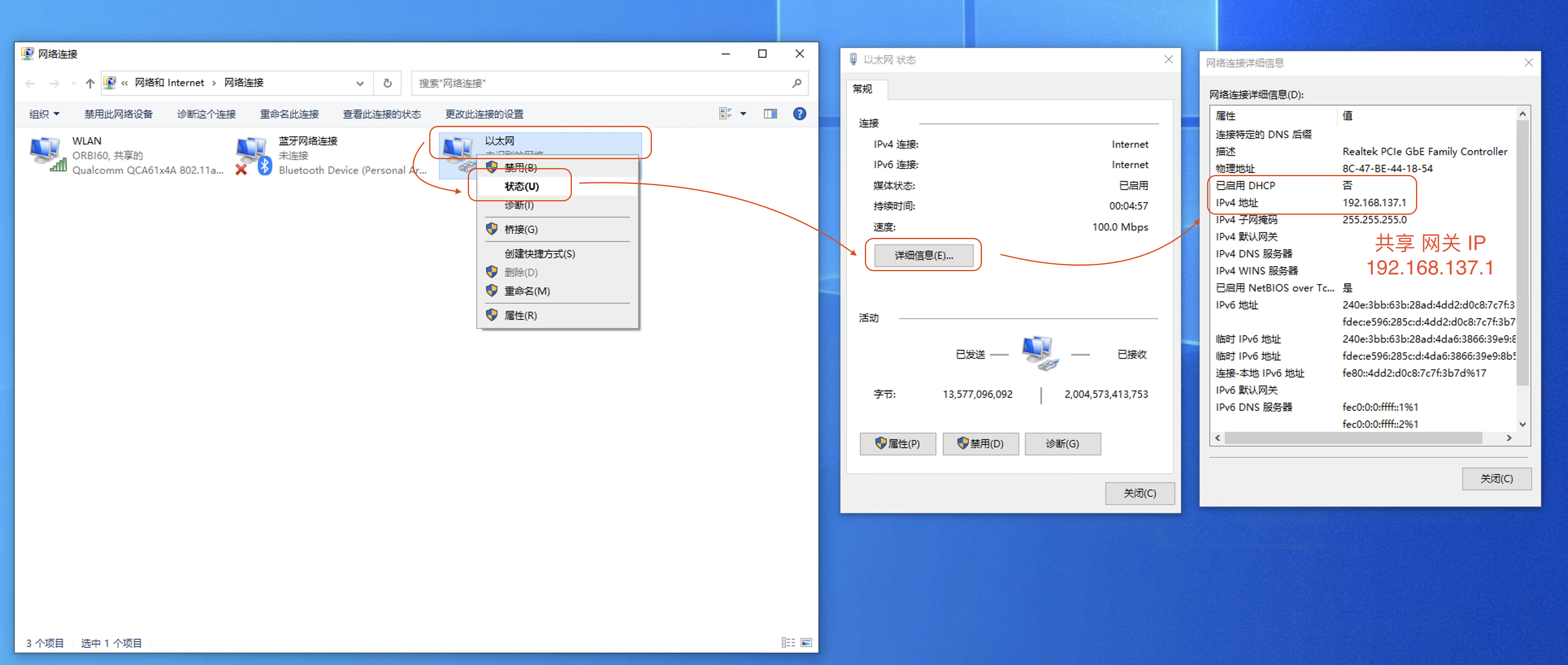
- Finally, connect the computer's
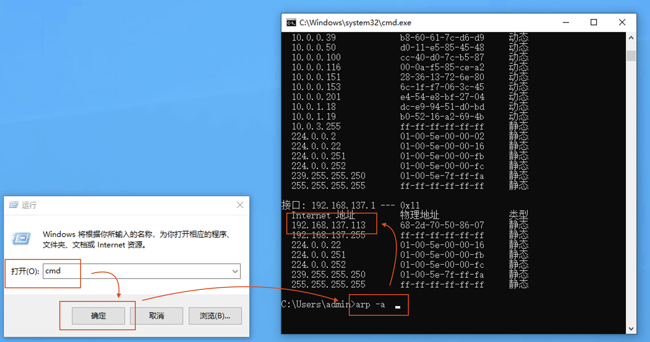
Ethernetto the device and usearpto find the device's shared IP
Usually 192.168.137.x
Exclude 192.168.137.1 (
Ethernet gateway )Exclude 192.168.137.255 (
broadcast address )
Win + R cmd
arp -a

接口: 192.168.137.1 --- 0x11
  Internet 地址         物理地址              类型
  192.168.137.113       68-2d-70-50-86-07     静态
  192.168.137.255       ff-ff-ff-ff-ff-ff     静态
Tools
RKISP_Tuner_v3.4.1_Alpha.rar
Link: https://pan.baidu.com/s/13rAs9o6qNYz8sBR69DRR1w?pwd=fanc
Extraction code: fanc Copy this content and open the Baidu Netdisk mobile app for a more convenient operation
Password Related
ssh
Usually just root@[ip]
ssh root@[ip]
Connecting via Network IP adb
adb connect [ip]

adb shell

# Set the root password for the first time
passwd
Wired USB Connection
adb shell

# Set the root password for the first time
passwd
WEB Page
The default account password is
Account: admin
Password: admin
Development and Debugging
Build Debian Command
You need to set a variable; everything else stays the same
export RK_ROOTFS_SYSTEM=debian
How to View Logs
- Usually it means the camera is not plugged in, or was not recognized correctly
After adb shell, logcat | grep imx415 or logcat | grep imx307 to view the driver loading information for the corresponding imx-series camera
If there is no logcag, use dmesg | grep imx415 or dmesg | grep imx307
If there is no loading information, it means there is no camera or it was not recognized properly. Reference information:
Log Reference / Streaming Abnormalities
While streaming,
Taking imx415 as an example, the normal loading log is:
If you cannot understand it, try copying the log to an AI for analysis
## The kernel successfully read the chip ID (0000e0) of the imx415 sensor over the I2C bus, indicating that the hardware connection is normal and the sensor has responded. This is the key sign of successful loading.
Jan  1 00:00:01 rv1126bp-buildroot kern.info kernel: [    1.221046] imx415 1-0010: Detected imx415 id 0000e0

## Suggests that the developer consider updating the imx415 driver to more strictly match the endpoints defined in the Device Tree. This is only an advisory warning and does not affect current operation; it is usually caused by a slight difference between the port/endpoint configuration in the device tree and what the driver expects, but the existing configuration still allows the camera to work.
Jan  1 00:00:01 rv1126bp-buildroot kern.notice kernel: [    1.221082] imx415 1-0010: Consider updating driver imx415 to match on endpoints

## Rockchip's MIPI CSI-2 D-PHY controller (csi2-dphy0) successfully matched the imx415 sensor with bus type 5. This indicates that the physical layer (D-PHY) for image data transmission has been correctly bound to this camera and image data can be received normally.
Jan  1 00:00:01 rv1126bp-buildroot kern.info kernel: [    1.221100] rockchip-csi2-dphy csi2-dphy0: dphy0 matches m00_b_imx415 1-0010:bus type 5
Camera Shows Green / Smearing
-
Please update Image Quality
you can copy it directly to the mainboard to replace -
You can also put it into the SDK and rebuild the firmware
-
You can also flash the latest firmware, where this is already fixed
Located in Downloads / RV1126BP / 01.Hardware Resources / Sensors / Image Quality
cp imx415_CMK-OT1948-PV1_styleDahP0_test.json /etc/iqfiles/imx415_default_default.json

cp imx307_CMK-OT0837-PT2_YT-2929_UNV-40IRC-2M-F20_test.json /etc/iqfiles/imx307_default_default.json