Interface Definitions

The DC865 provides a rich set of interfaces, as shown in the following diagram:
Overall Interface Diagram
Overall Device Interfaces
J1 TYPE-C Multifunctional Port
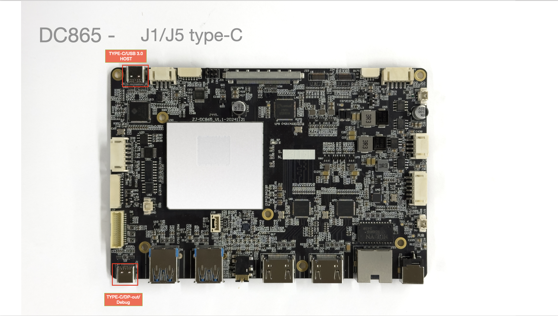
- TYPE-C Port: The DC865 control board provides a TYPE-C interface for module system firmware upgrade, supporting DP out / Debug.
J2/J4 Power Supply
Connection Method
Pin Definitions J4
| Pin No. | Pin Description | Wire Color (Reference) | Notes |
|---|---|---|---|
| 1 | GND | Black | Ground |
| 2 | GND | Black | Ground |
| 3 | 12V | Red | Operating Voltage 12V |
| 4 | 12V | Red | Operating Voltage 12V |
Connect to a 12V Power Supply
- Supports
DC 12V 4PINpower connector
Measured Power Consumption
-
Test Method:
- Flash the default
Androidfirmware. - Power on normally, unlock the screen, and perform no other operations.
- Measure only the motherboard power; the backlight is not connected.
- Flash the default
| State | Voltage | Current | Power | Notes |
|---|---|---|---|---|
| Normal boot, no screen connected | 12.4V | 0.2A | Standby 2.3-3.1W | Measurement accuracy 0.1 |
J5 TYPE-C USB 3.0 Full-Featured Port
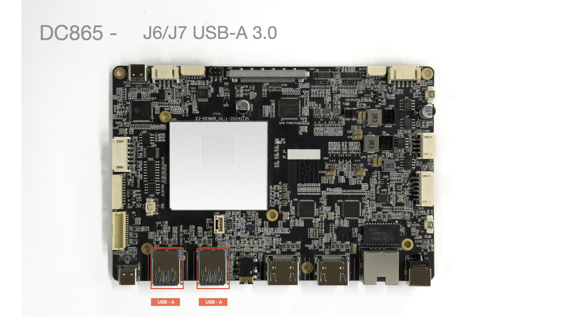
- TYPE-C Port: USB 3.0 HOST.
J6/J7 USB Ports
- Supports 2x standard USB-A 2.0 ports.
J8 USB Port
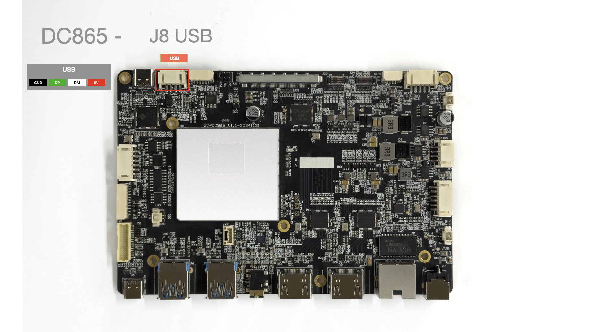
| Pin No. | Pin Description | Wire Color (Reference) | Notes |
|---|---|---|---|
| 1 | GND | Black | Ground |
| 2 | DP | Green | |
| 3 | DM | White | |
| 4 | 5V | Red | 5V |
J9 5G Module
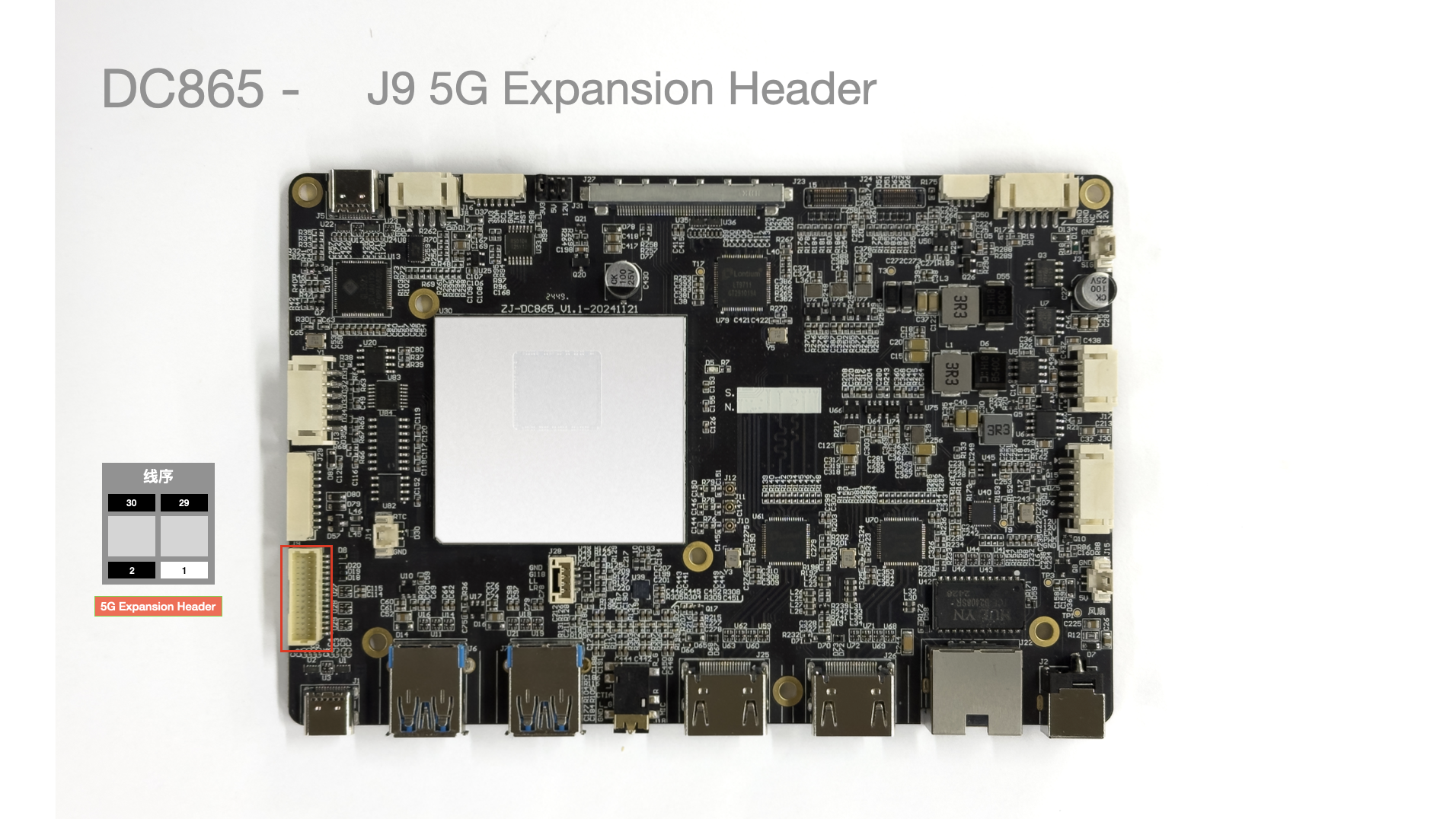
- See specification for details.
J10/J11/J12 WIFI Bluetooth Antenna
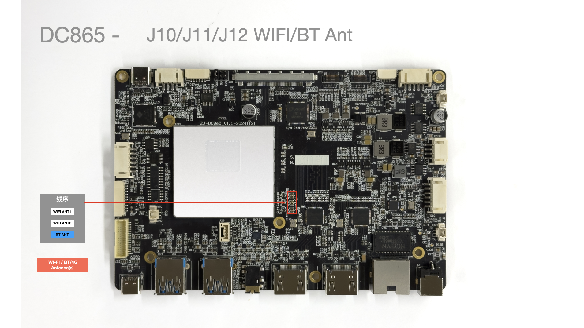
J13 Panel Button Interface
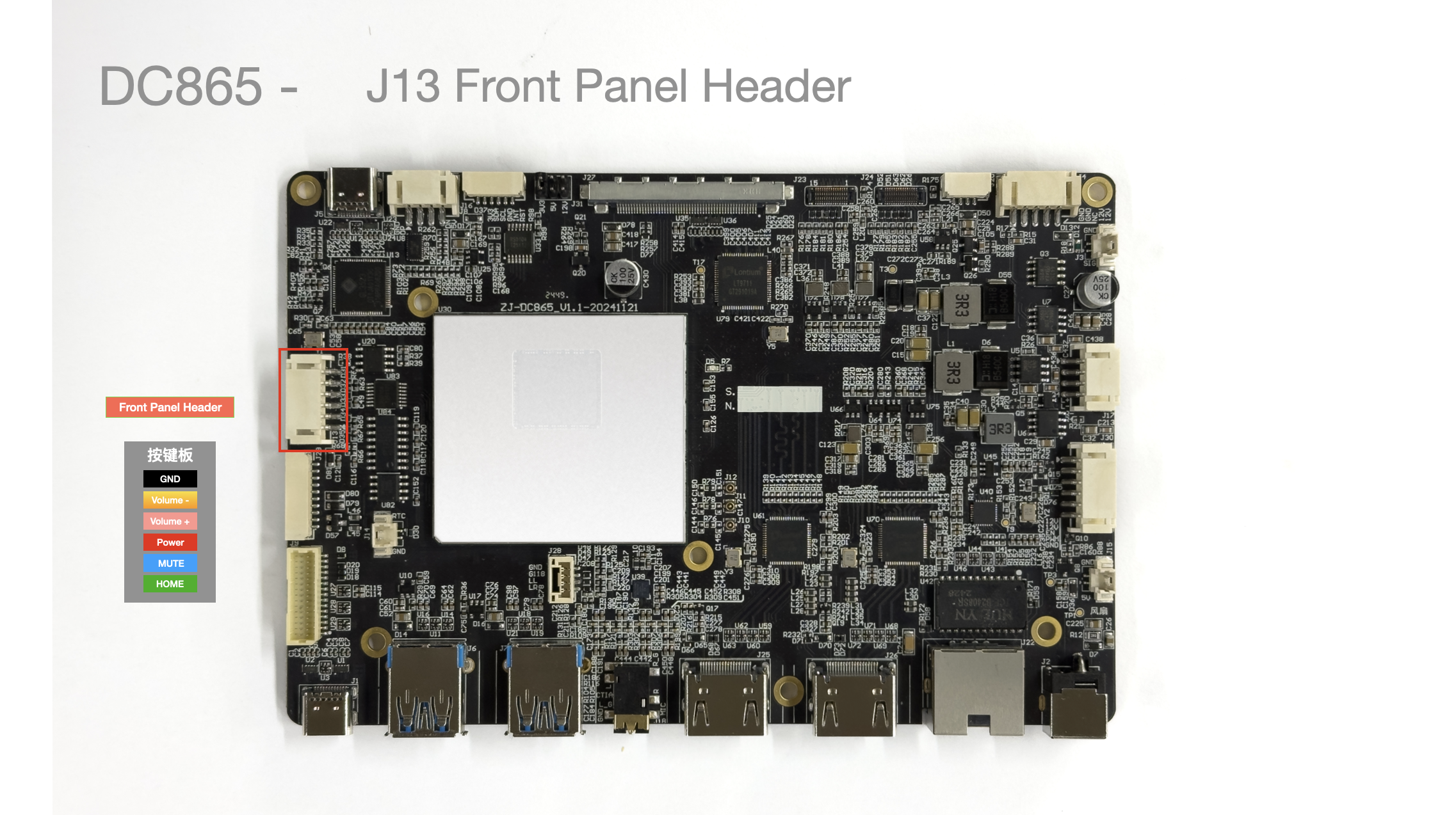
| Pin No. | Pin Description | Notes |
|---|---|---|
| 1 | HOME | |
| 2 | MUTE | |
| 3 | PWRKEY | |
| 4 | KEY_VOL_UP | |
| 5 | KEY_VOL_DOWN | |
| 6 | GND |
J14 RTC
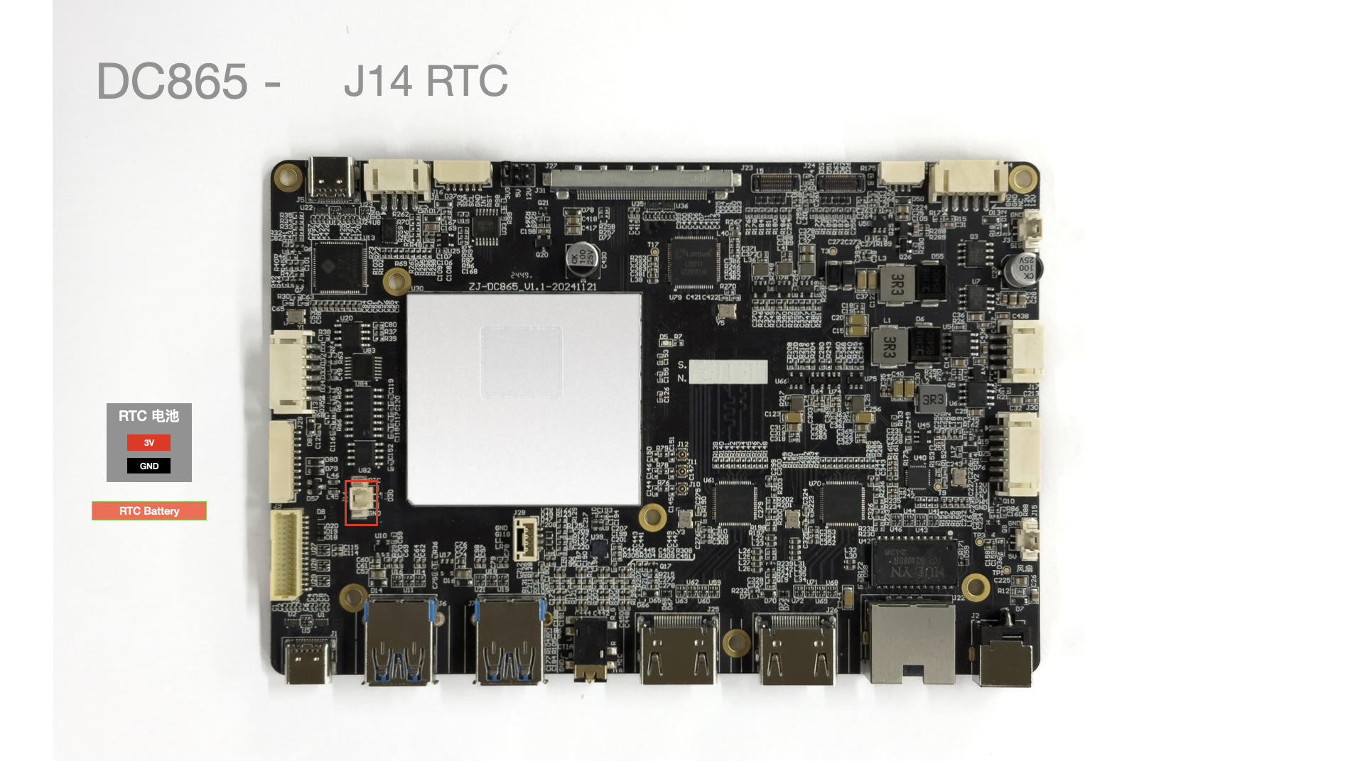
| Pin No. | Pin Description | Notes |
|---|---|---|
| 1 | 3.3V | |
| 2 | GND |
J15 Fan Interface
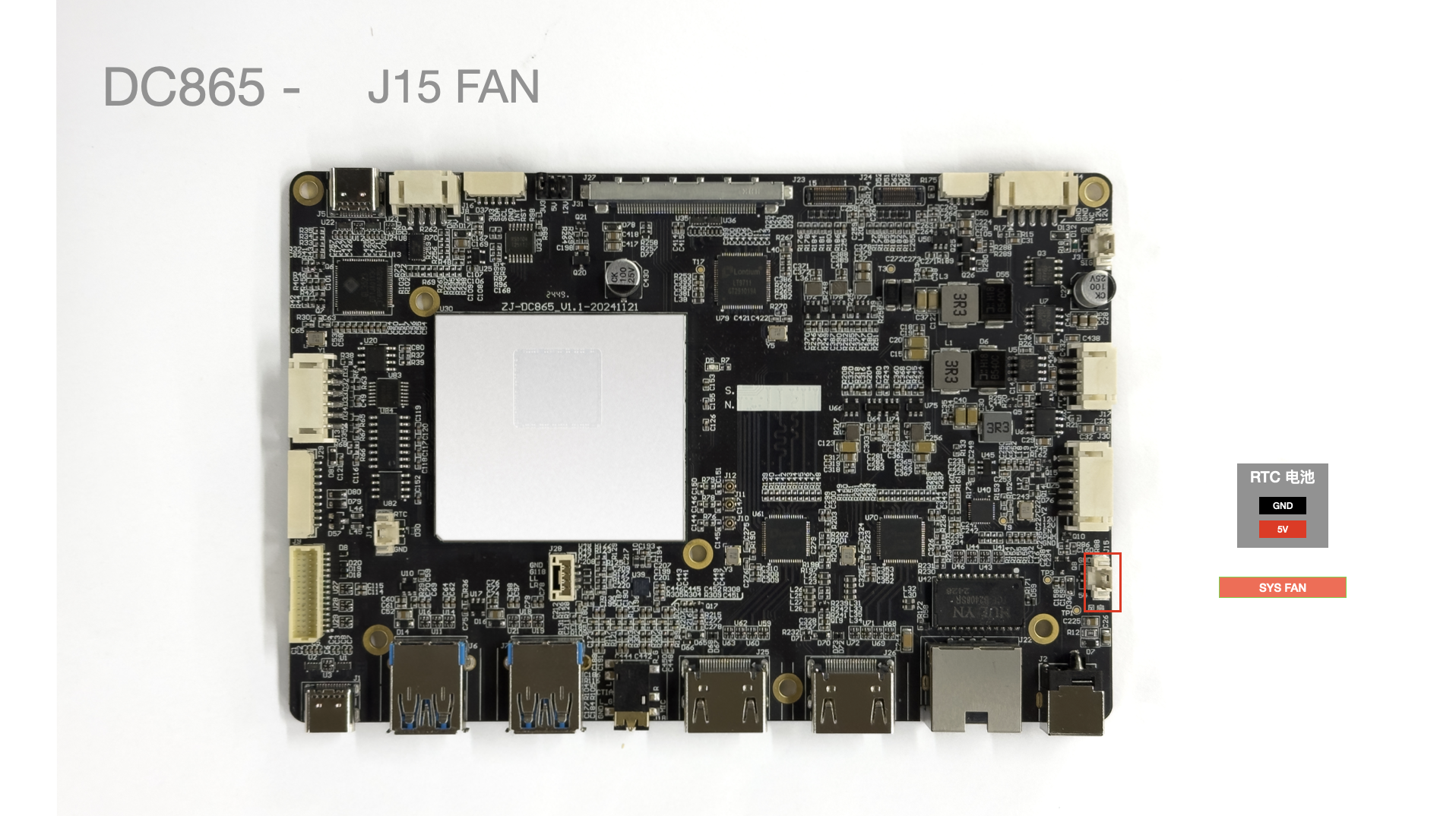
| Pin No. | Pin Description | Notes |
|---|---|---|
| 1 | 5V | |
| 2 | GND |
J16 I2C Interface
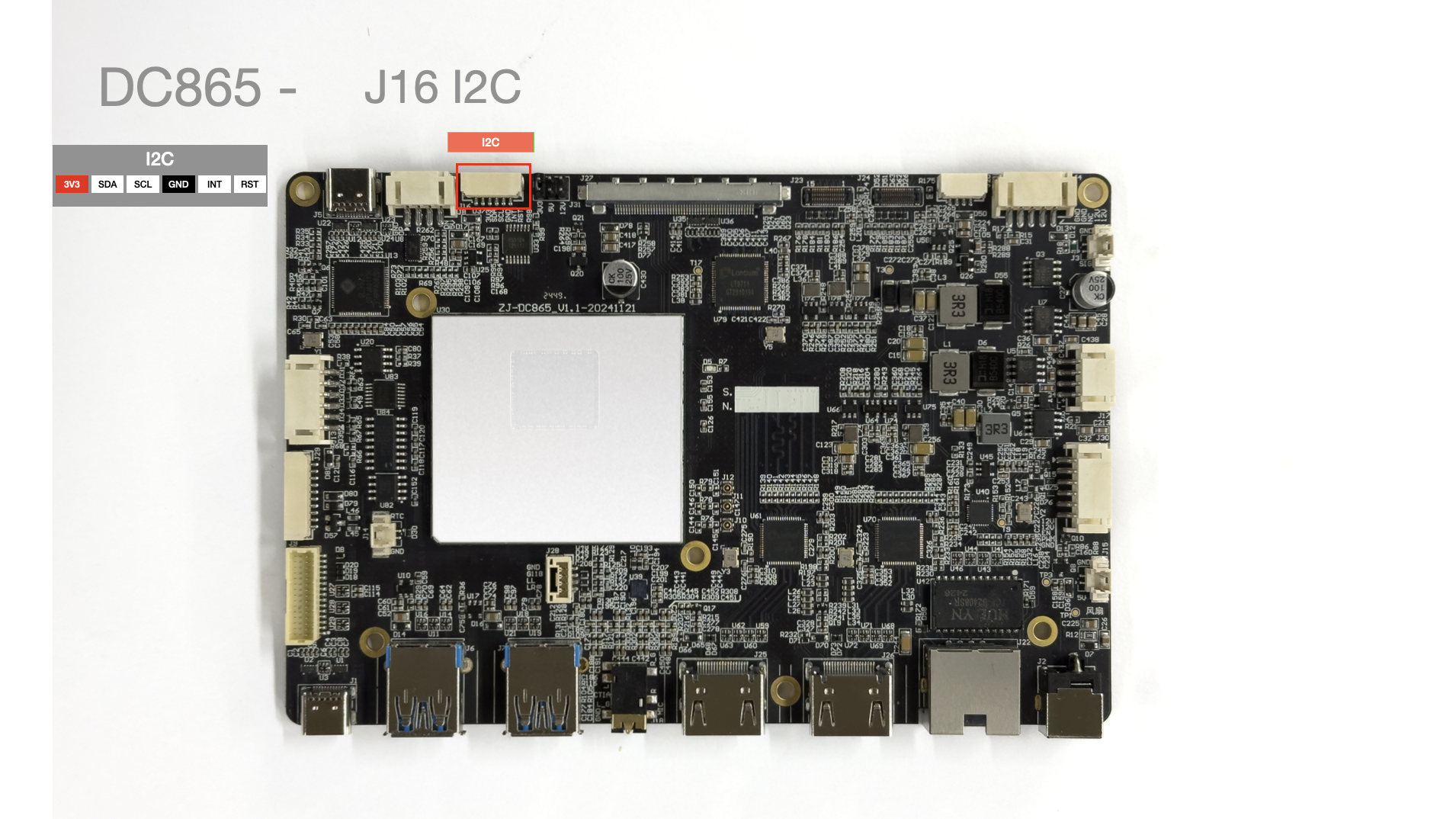
| Pin No. | Pin Description | Notes |
|---|---|---|
| 1 | 3V3 | |
| 2 | SDA | |
| 3 | SCL | |
| 4 | GND | |
| 5 | INT | |
| 6 | RST |
J17 AUDIO_OUT Interface
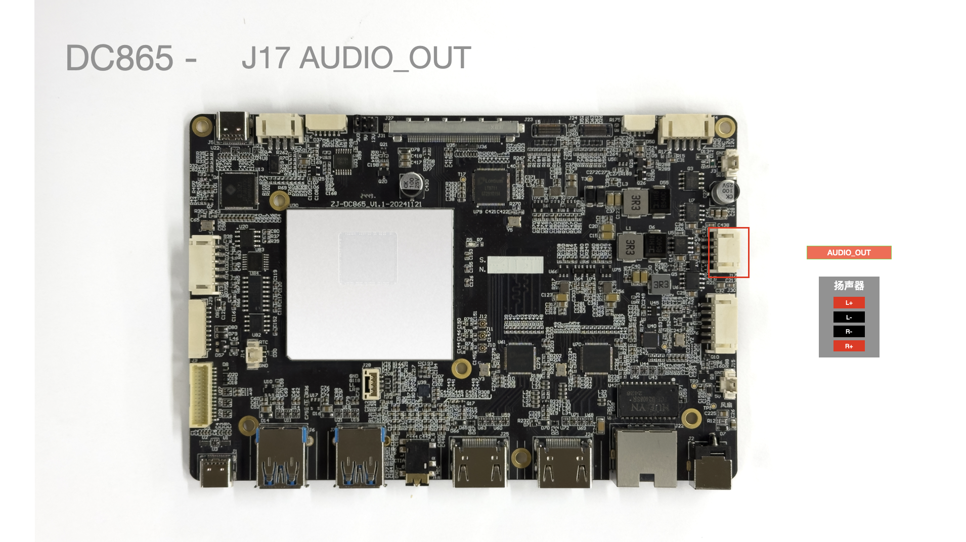
| Pin No. | Pin Description | Notes |
|---|---|---|
| 1 | Left Channel + | |
| 2 | Left Channel - | |
| 3 | Right Channel - | |
| 4 | Right Channel + |
J18 Headphone Jack
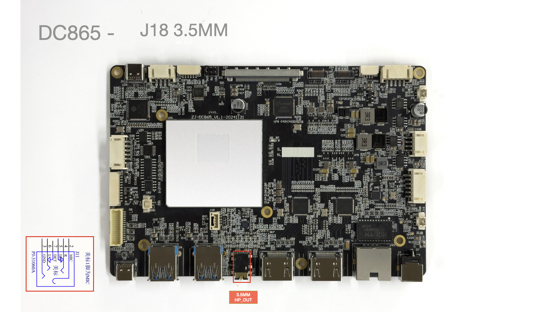
- American standard headphone jack.
J20 12V LED Strip
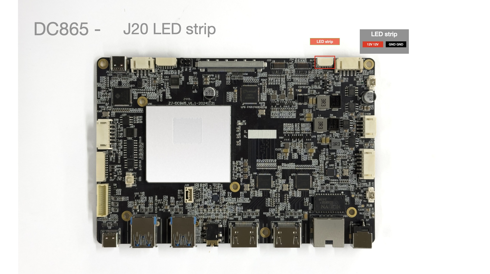
| Pin No. | Pin Description | Notes |
|---|---|---|
| 1 | 12V | |
| 2 | 12V | |
| 3 | GND | |
| 4 | GND |
J22 Ethernet Port
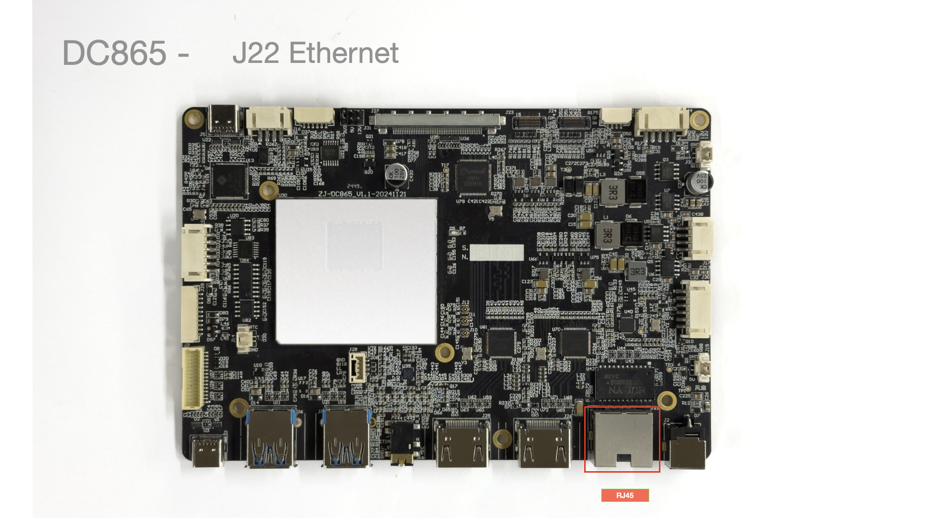
- Speed: 1000Mbps
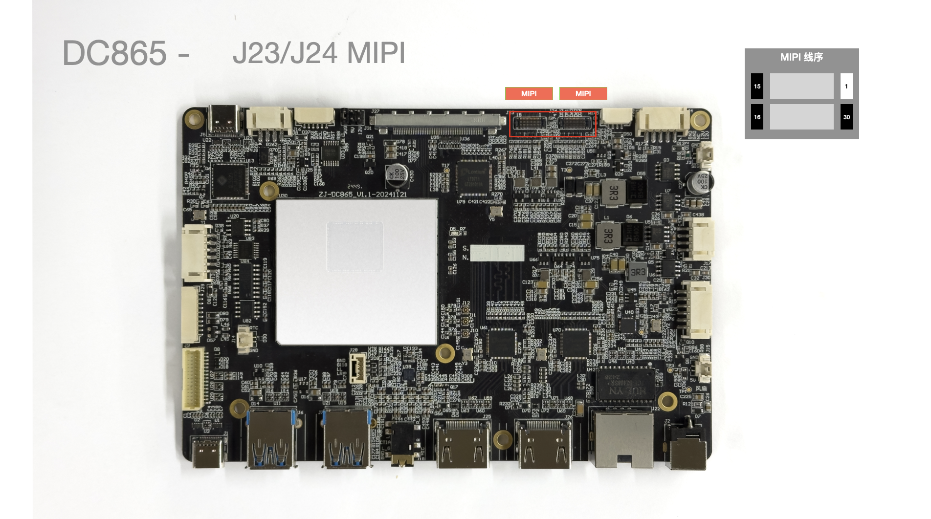
J23 MIPI Camera Interface
J25/J26 HDMI-IN
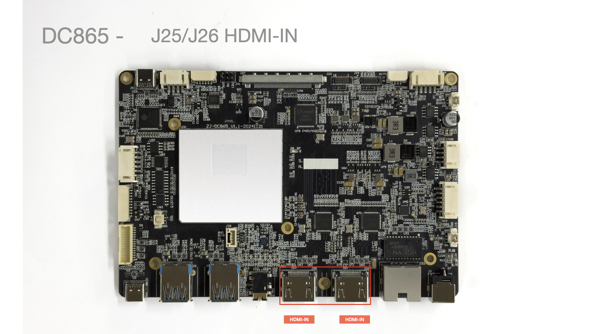
- HDMI IN input interface, supports HDMI audio. Supported resolutions: 1920X1080@60fps, 2560x2048@30fps, 3840*2160@30fps.
J27 eDP Screen Interface
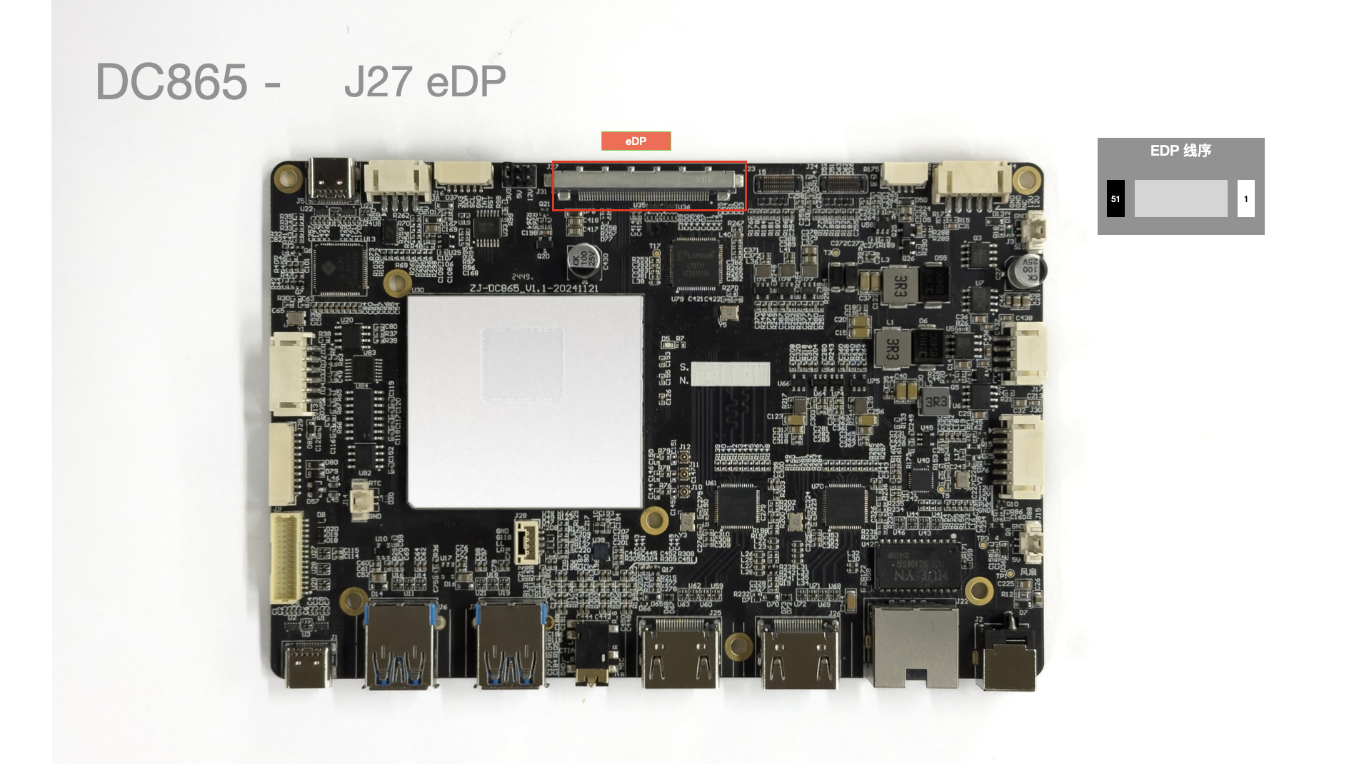
Supports resolution up to 3820X2160@60fps.
J28 MIC Interface
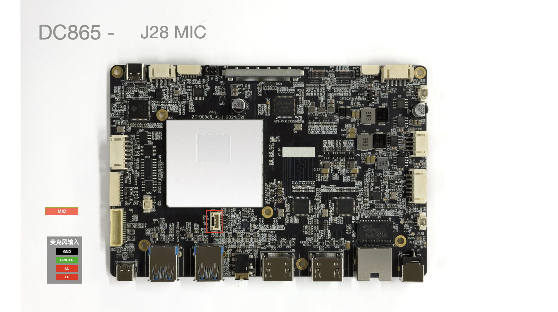
| Pin No. | Pin Description | Notes |
|---|---|---|
| 1 | LR | |
| 2 | LL | |
| 3 | GPIO118 | |
| 4 | GND |
J29 Serial Port
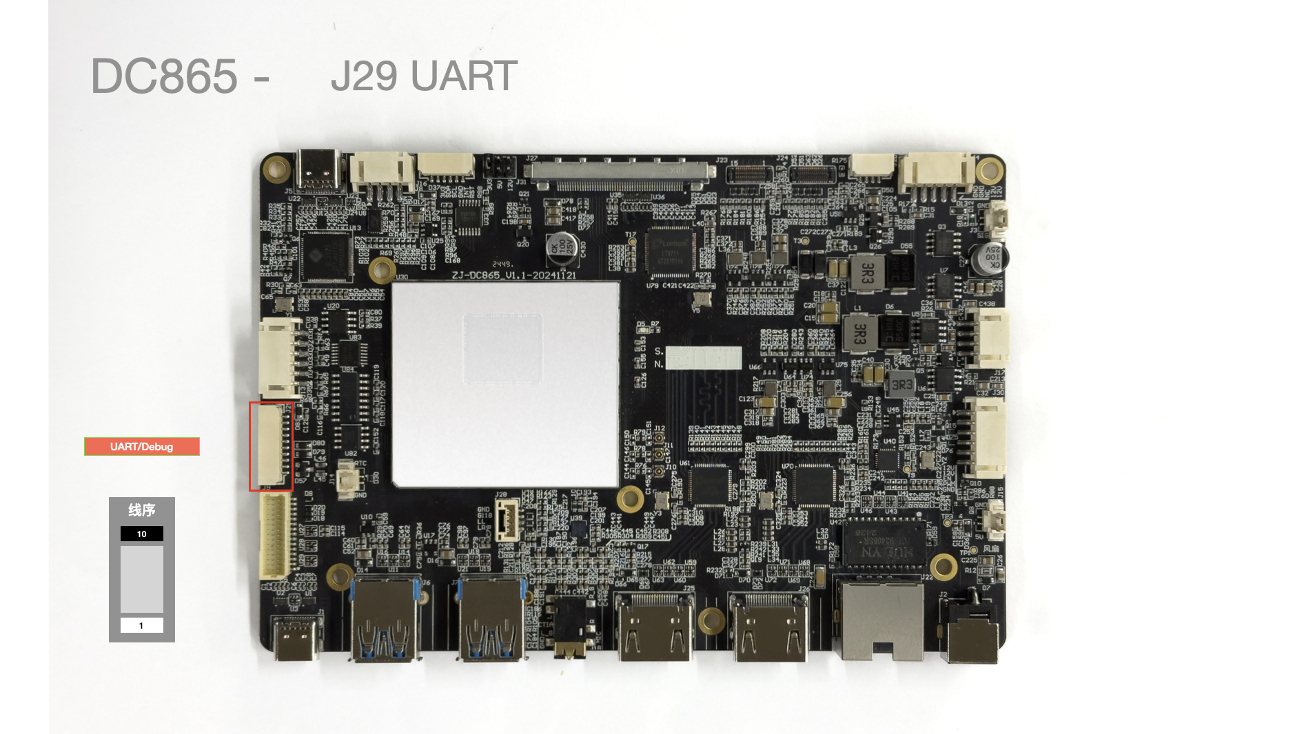
| Pin No. | Pin Description | Notes |
|---|---|---|
| 1 | RS485_B | |
| 2 | RS485_A | |
| 3 | GND | |
| 4 | RS232_TX1 | |
| 5 | RS232_RX1 | |
| 6 | GND | |
| 7 | GPIO119 | |
| 8 | GPIO120 | |
| 9 | GND | |
| 10 | 5V |
J30 Backlight Power Supply
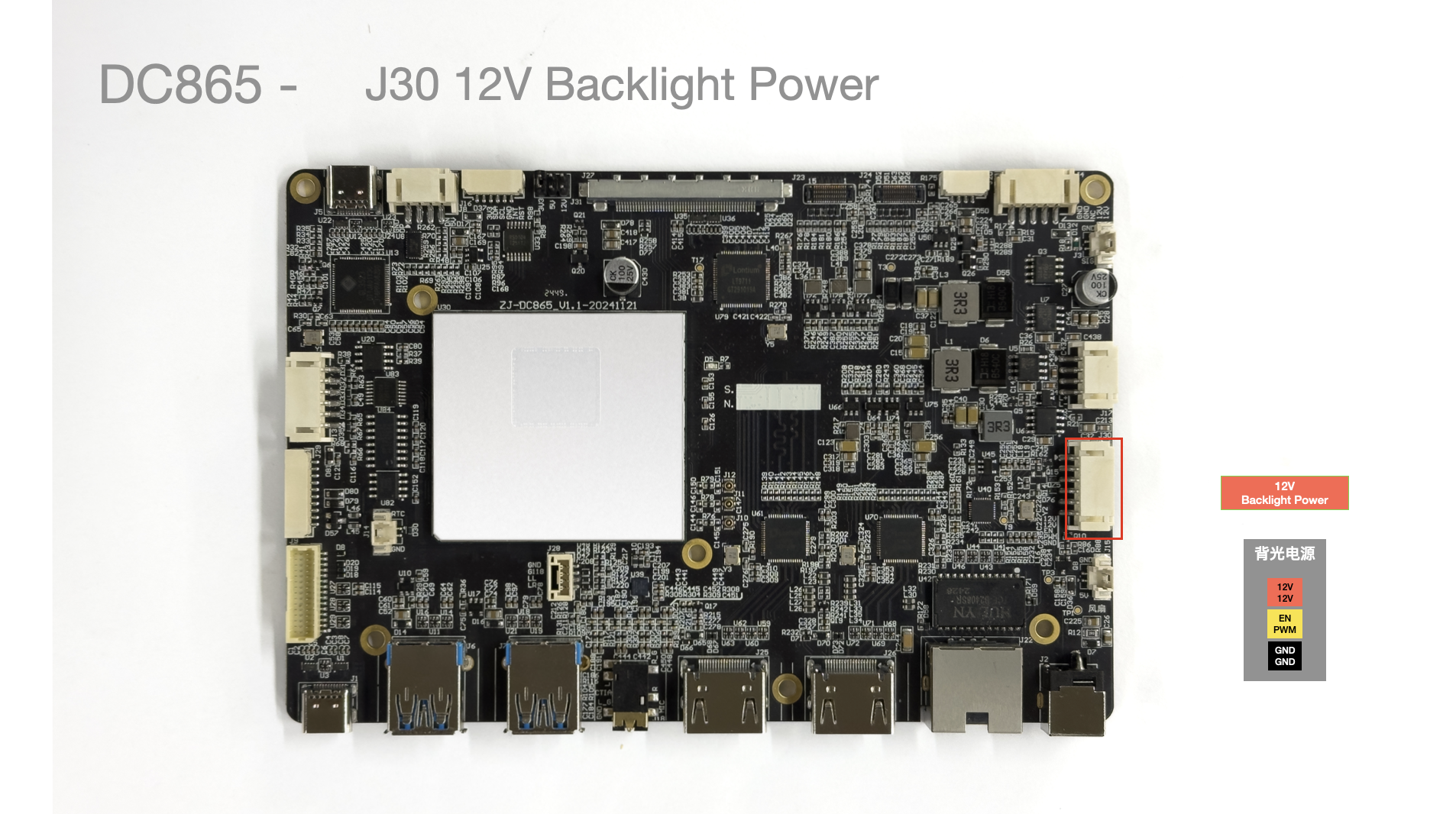
| Pin No. | Pin Description | Wire Color (Reference) | Notes |
|---|---|---|---|
| 1 | 12V | Red | Operating Voltage 12V |
| 2 | 12V | Red | Operating Voltage 12V |
| 3 | BL_EN | Yellow | Backlight Control |
| 4 | BL_PWM | Yellow | Backlight Control |
| 5 | GND | Black | Ground |
| 6 | GND | Black | Ground |
- Maximum
3A Max
J31 eDP Power Selection Interface
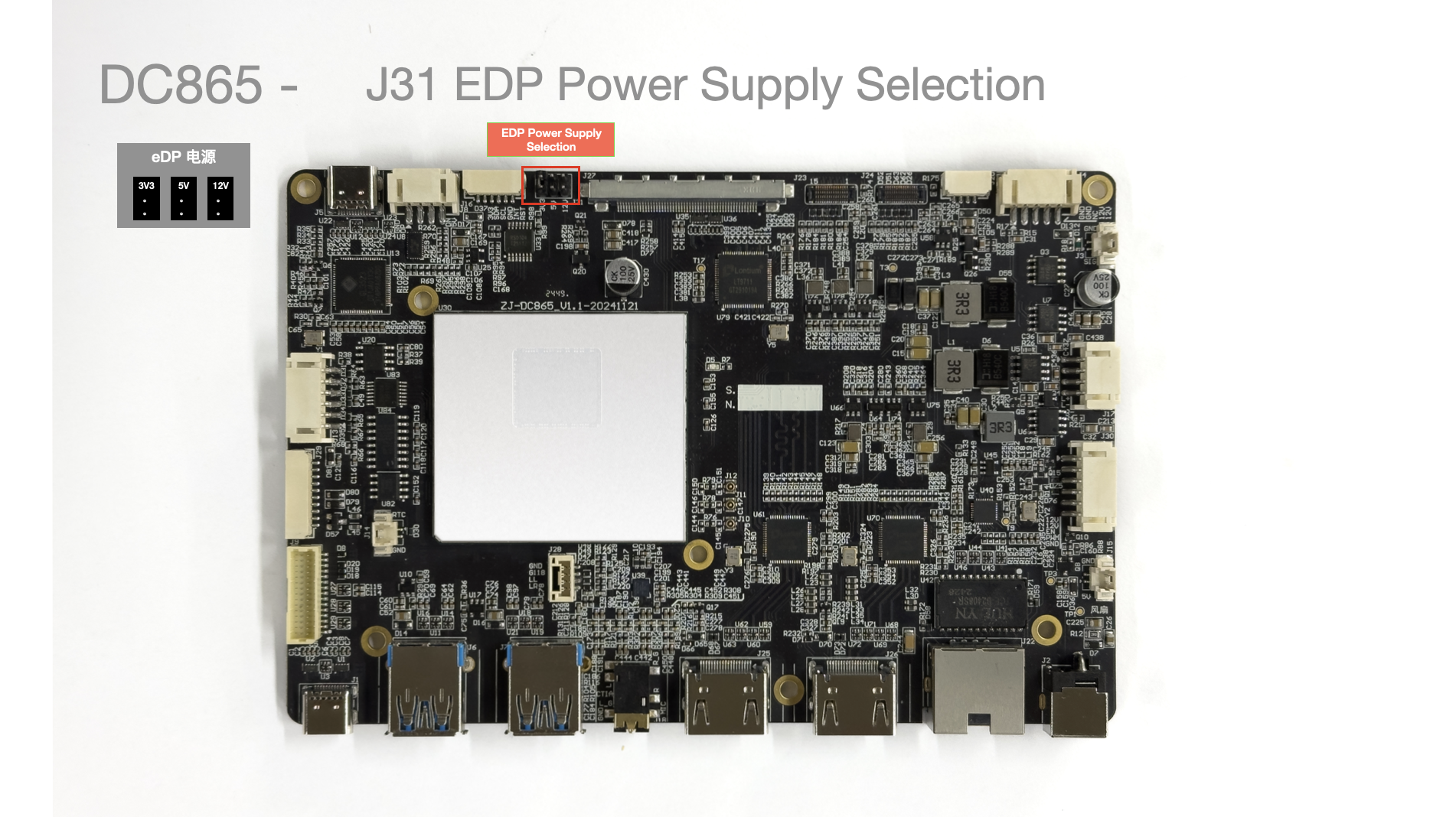
| Pin No. | Pin Description | Notes |
|---|---|---|
| 1 | 3.3V | Jumper selects voltage |
| 2 | 3.3V | Jumper selects voltage |
| 3 | 5V | Jumper selects voltage |
| 4 | 5V | Jumper selects voltage |
| 5 | 12V | Jumper selects voltage |
| 6 | 12V | Jumper selects voltage |
S1/S2 I2C Interface
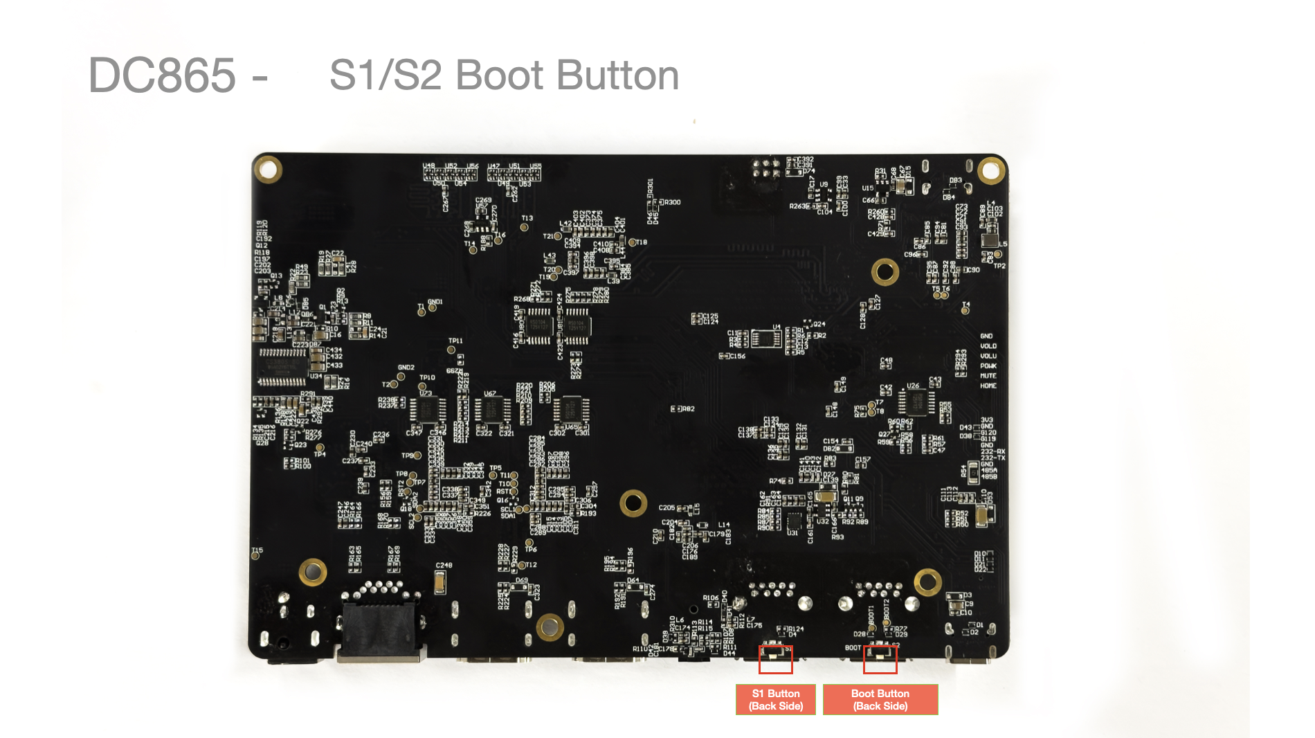
| Interface | Pin Description | Notes |
|---|---|---|
| S1 | GPIO_59 | Currently undefined |
| S2 | Boot | Burning mode |
S2: Located below the J6 USB interface, used to enter burning mode.
Usage: Press and hold this button before powering on, then release after powering on to enter burning mode.