Quick Installation

DC690 Wiring Guide
The differences between the following DC690 versions are reflected in:
Quick Connections
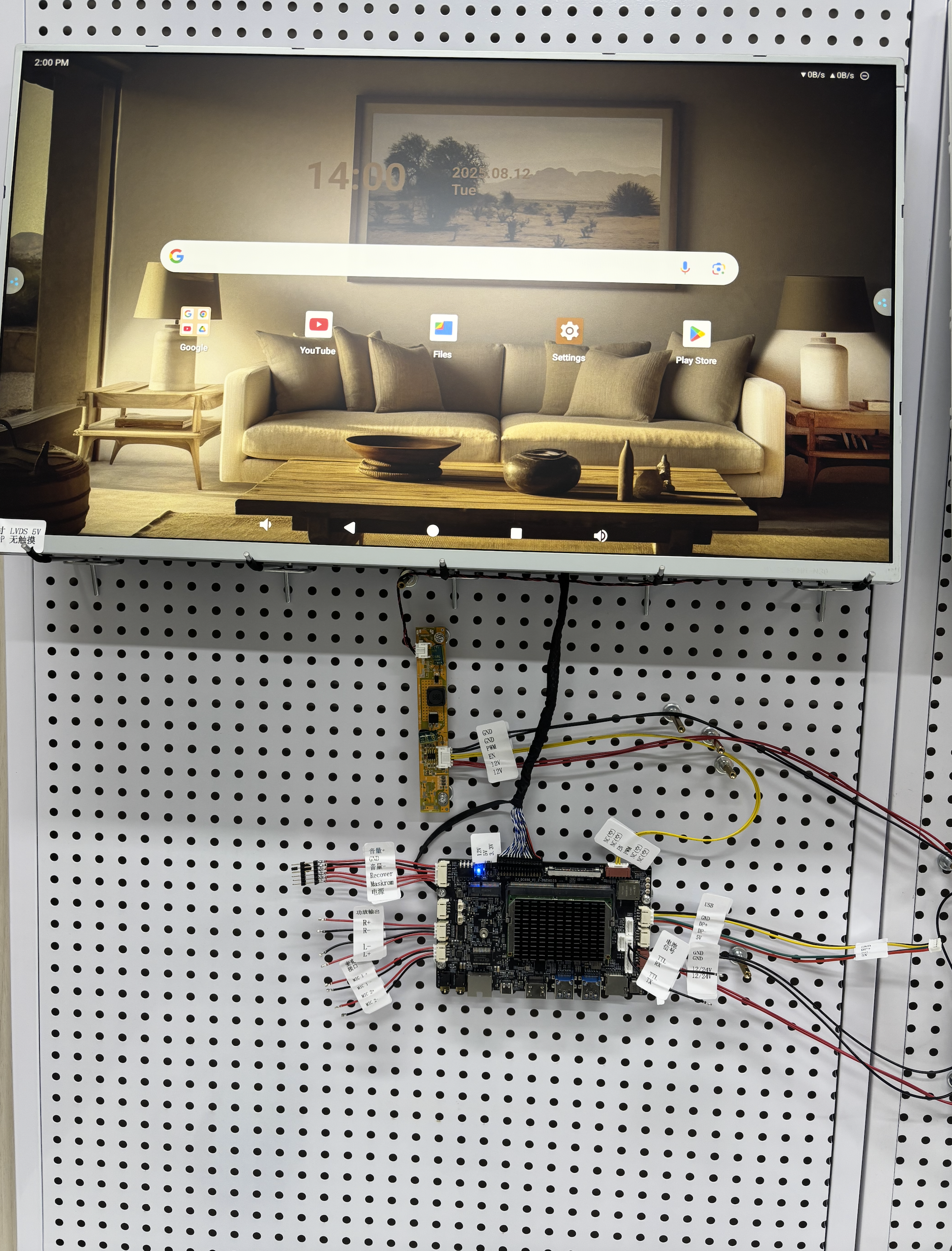
Refer to the overall wiring diagram.
Main View
View the overall connection effect.
Overall View
Power Supply Section
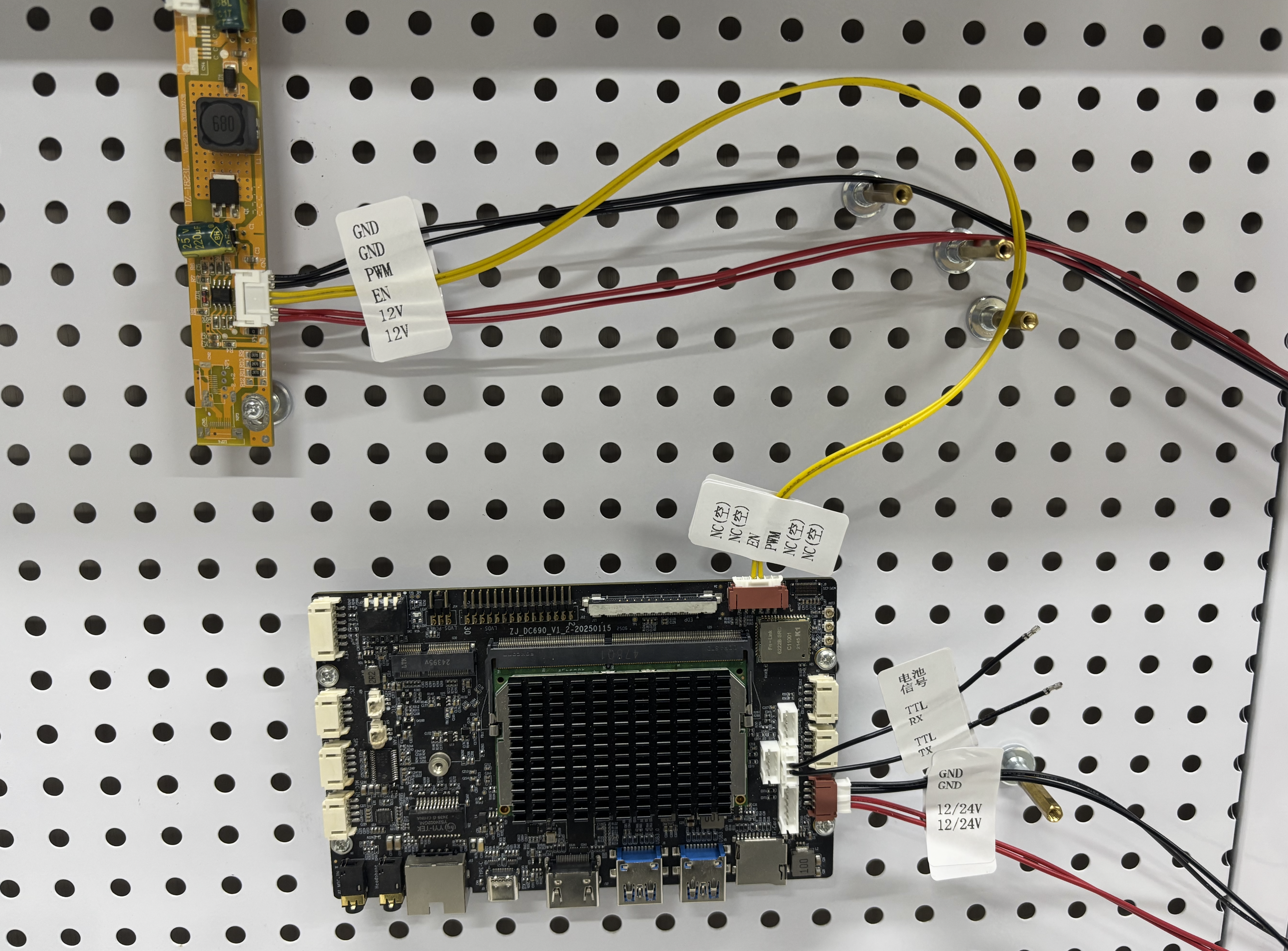
Please refer to the diagram for power supply connections.
-
Note: For screens
27 inches /4K screens and above, please follow the diagram anduse an independent power supply for optimal performance. -
For
J14, the constant current board and the motherboard only need to connectPWMandEN.
Power Supply Wiring Diagram
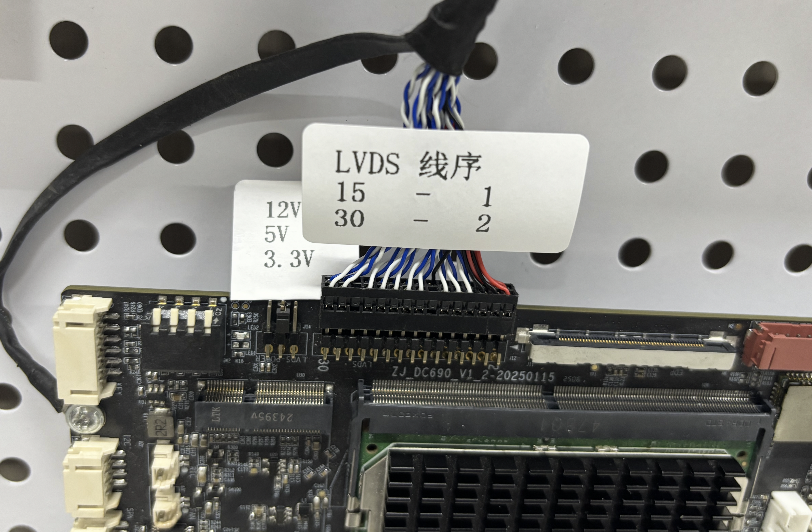
LVDS Connector
-
When connecting to
J12for LVDS, please note that the correct orientation is with thePin 1 markerfacing down. -
Select
LVDS-POWERonJ14according to your screen specifications.
Note: The
Pin 1 markeron the LVDS cable should face down.
Main Connections
Power Supply Connector
-
The red connector
J1is for the main power supply.- Caution:
Do not reverse the polarity.
- Caution:
-
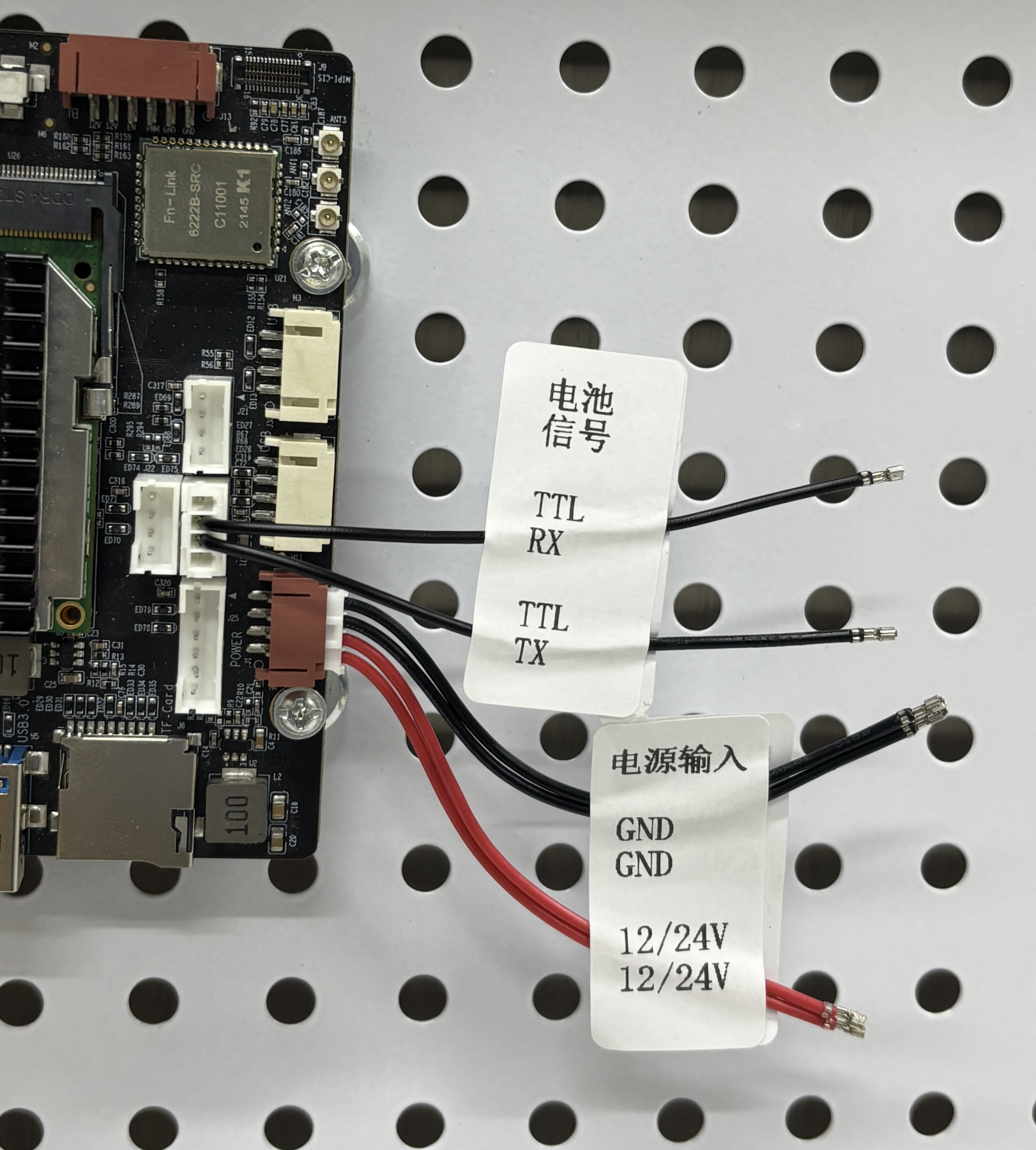
The
RXandTXpins on the white connectorJ24are for battery communication, used to obtain batterylevelandcharginginformation.-
GNDdoes not need to be connected, as it is shared with the main power supplyGND. -
These can be left unconnected if battery level information is not needed or supported.
-
Power Supply Section
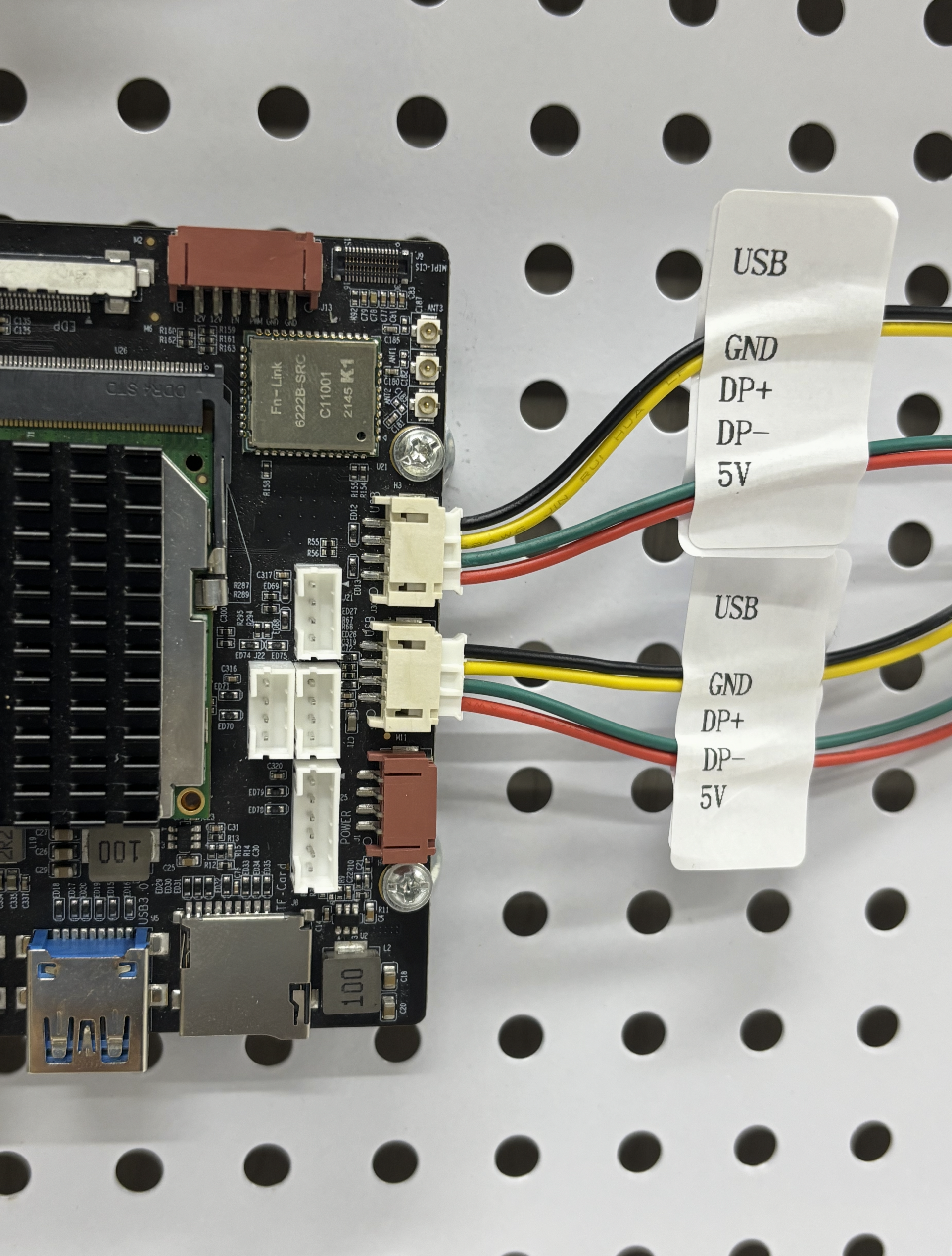
Internal USB Connectors
J7andJ30are two onboard standard 4-pin USB connectors.
Internal USB Wiring
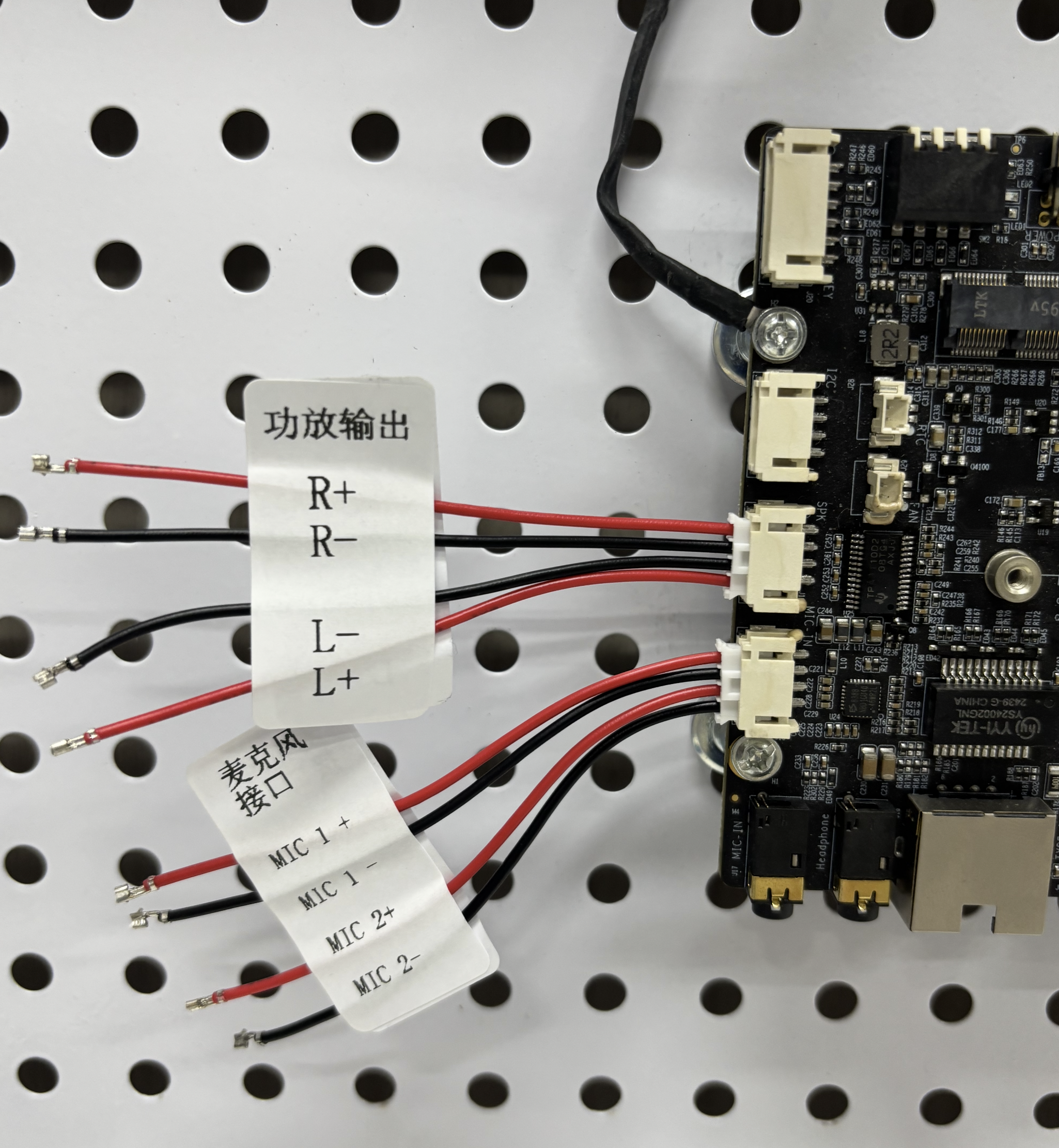
Microphone and Amplifier Connectors
-
J18MIC-IN: Ensure correct polarity to avoid low volume. -
J192x15W amplifier output, supports8 Ohm 15W.L: Left channel, R: Right channel.
Microphone and Speaker Connectors
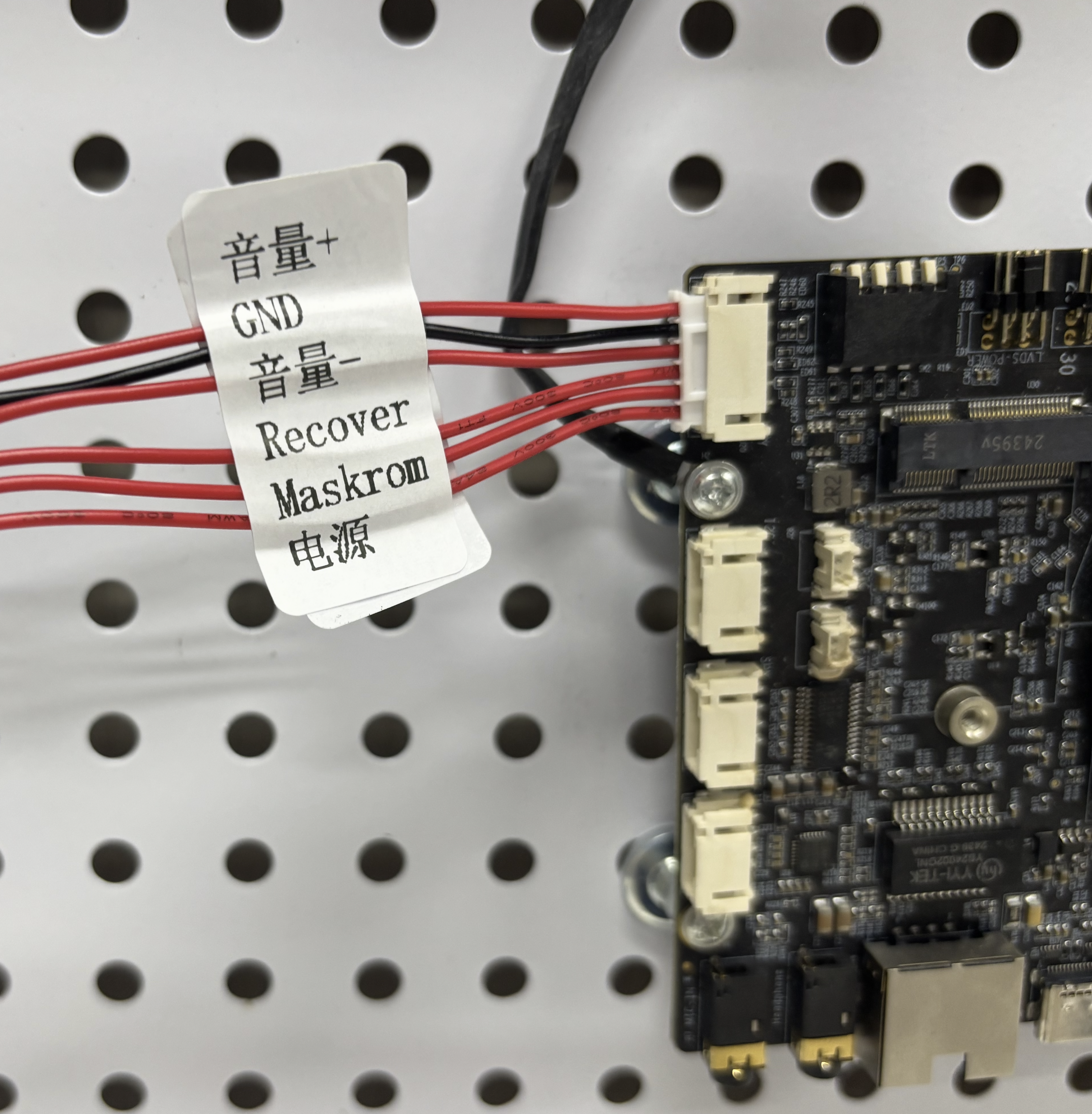
Panel Buttons
J20Button Connections:
| Pin Connection | Function |
|---|---|
Pin 2 + Pin 1 | Volume + |
Pin 2 + Pin 3 | Volume - |
Pin 2 + Pin 4 | Recovery |
Pin 2 + Pin 5 | MaskRom |
Pin 2 + Pin 6 | Power |
To upgrade the system, press and hold the MaskRom button while connecting to enter USB flashing mode.
Pin 2 is GND
Screen Buttons
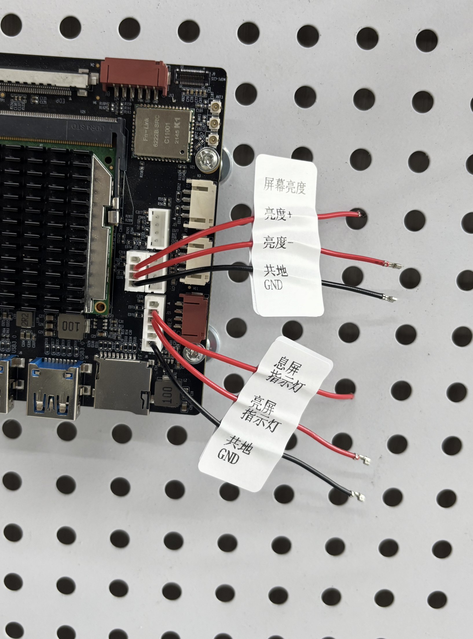
J22Screen Buttons:
| Pin Connection | Function |
|---|---|
Pin 4 + Pin 2 | Screen Brightness + |
Pin 4 + Pin 3 | Screen Brightness - |
J25Screen Indicator Lights:
| Pin Connection | Function | Reference |
|---|---|---|
Pin 6 + Pin 2 | High when screen off | Connect a red light to indicate screen-off status |
Pin 6 + Pin 3 | High when screen on | Connect a blue light to indicate screen-on status |
Brightness Buttons and Screen-off Indicator